Circuit terminology
We are developing methods for analyzing a circuit. So far we’ve defined the most common components (resistor, capacitor, and inductor) and sources (voltage and current). Now we need a crisp vocabulary to talk about circuits. This article is a glossary of terms and concepts we use in circuit analysis and design.
Contents
Where we’re headed
Definitions and concept checks for important features of a circuit, including,
- Symbols
- Wires (lines) and junctions (dots)
- Node and Branch
- Loop and Mesh
- Reference node (ground)
Circuit terms
Circuit
Circuit comes from the word circle. A circuit is a collection of components, power sources, and signal sources, all connected so current can flow in a complete circle. You can also call a circuit a network.
Closed circuit
A circuit is closed if the circle is complete, if all currents have a path back to where they came from.
Open circuit
A circuit is open if the circle is not complete, if there is a gap or opening in the path.
Short circuit
A short is a path of low resistance. It is usually by mistake. The resistor shown below is the intended path for current, and the curved wire going around it is the short. Current is diverted away from its intended path, sometimes with damaging results. The wire shorts out the resistor by providing a low-resistance path for current (probably not what the designer intended).

Make or break
You make a circuit by closing the current path, such as when you close a switch. Breaking a circuit is the opposite. Opening a switch breaks the circuit.

The phrase “make or break situation” means whatever happens the outcome is definitely going in one of two directions.
Schematic terms
Schematic
A schematic is a drawing of a circuit. A schematic represents circuit elements with symbols and connections as lines.
Elements and components
The term element means a component or a source. The term component refers to resistors, capacitors, inductors, transistors, etc. I typically don’t include sources when I say component.
Symbols
Elements are represented in schematics by symbols. Here are the symbols for the common 2-terminal elements.

Lines
Connections between elements are drawn as lines, which we often think of as “wires.” When drawn on a schematic, lines represent perfect conductors with zero resistance. Every component or source terminal touched by a line has the same voltage.
Dots
Connections between lines can be indicated by dots. Dots are an unambiguous indication that lines are connected. If the connection is obvious, you don’t have to use a dot.

(a) and (b) are both good. (c) no dot indicates no connection.
(d) also indicates no connection; the horizontal wire “hops” over the vertical wire.
(d) is very clear but takes extra effort and space to draw.
For crossing connected lines, (e) is acceptable, but risks looking too much like (c), so (f) is the better practice.
Reference Designator
When you place an element in a schematic you often give it a unique name, known as a reference designator. Examples of reference designators are $\text{R1}$, $\text{C6}$, and $\text{V}_\text{BAT}$. The $1$ in $\text{R1}$ is part of the name, and does not indicate the resistance value. Reference designators are by definition unique for each schematic. They let you identify components by name even if some of them have the same value. It is okay to use reference designators in equations. $\text{R1}$ can be assigned a resistance value, $\text{R1} = 4.7\,\text k\Omega$, and it can be used as a variable in expressions, as in $\text{R2} \cdot \text{C6} = 4.7\,\text k\Omega \cdot 2\,\mu\text F$.

Reference designators give elements unique names—even if their values are the same.
Node
A junction where $2$ or more elements connect is called a node. The schematic below shows a single node (the black dot) formed by the junction of five elements (abstractly represented by orange rectangles).

Distributed node
Since lines on a schematic represent perfect zero-resistance conductors, there is no rule that says lines from multiple elements are required to meet in a single point junction. We can draw the same node as a distributed node like the one in the schematic below. These two representations of the node mean exactly the same thing.

A distributed node might be all spread out, with lots of line segments, elbows, and dots. Don’t be distracted, it is all just one single node. Connecting schematic elements with perfect conductors means the voltage everywhere on a distributed node is the same.
Here is a realistic-looking schematic with the distributed nodes highlighted,

Problem 1: How many nodes are in this schematic?

3 nodes, 4 nodes, 5 nodes, 6 nodes, 8 nodes
show answer
There are $4$ nodes in the circuit.

$\goldC{\text{Node}\,1}$ is the junction between $\text V0$, and the bottom of $\text R3, \text R4$, and $\text R5$.
$\purple{\text{Node}\, 2}$ is the junction between the voltage source, $\text V0$, and resistor $\text R1$.
$\red{\text{Node} \, 3}$ is the junction between resistors $\text R1, \text R2$, and $\text R3$.
$\green{\text{Node}\,4}$ is the junction between resistors $\text R2, \text R4$, and $\text R5$.
other definitions of node
Depending on your textbook or web resource, you may come across other definitions of node. In some texts a node is defined as the junction between $3$ or more elements.
Another term you may come across is essential node. This also means a node with $3$ or more connected elements. In this teaching style, nodes have $2$ or more connections, and essential nodes have $3$ or more.
Here at Spinning Numbers, I use the definition where a node is the junction between $2$ or more elements. This $2$-element definition is used by circuit simulation programs like SPICE because every junction has to have a unique name.
All these shades of meaning have the same objective. There's no need to worry about which way is right. If you use another reference alongside Spinning Numbers, check the definition of node to see if it's the same as we use here.
Branch
A branch is a connection between nodes. A branch contains an element (resistor, capacitor, source, etc.). The number of branches in a circuit is the same as the number of elements.
Problem 2: How many branches are in this circuit?
3 branches, 4 branches, 5 branches, 6 branches
show answer
There are 6 branches in this circuit, one for each element,

other definitions of branch
A branch is a path between two nodes. Some texts define a node as a junction of $3$ elements. If that is the case, a branch between two nodes may be a single element or may include two or more elements in series (since they don’t count a 2-element junction as a node). If that’s the case, the number of elements and number of branches is not necessarily the same.
This alternate definition doesn’t cause problems because we don’t do anything with branch counts that makes a difference to circuit analysis. Just be aware that someone you are talking to may have a slightly different vocabulary than you.
Loop
A loop is any closed path going through circuit elements. To draw a loop, select any node as a starting point and draw a path through elements and nodes until the path comes back to the node where you started. There is only one rule: a loop can visit (pass through) a node only one time. It is ok if loops overlap or contain other loops. Some of the loops in our circuit are shown here. (You can find others, too. If I counted right, there are six.)

show all the loops
Six loops,

Just from this simple example you can see the number of loops in a circuit can become quite large. Loop analysis can be difficult—we put a lot of effort into figuring out simpler methods.
Mesh
A mesh is a loop that has no other loops inside it. You can think of this as one mesh for each “open window” of a circuit.
Problem 3: How many meshes are in this circuit?
1 mesh, 2 meshes, 3 meshes, 4 meshes
show answer
There are 3 meshes in the circuit, one for each “open window” in the circuit,

Reference Node
During circuit analysis we usually pick one of the nodes in the circuit to be the reference node. We assign a voltage of $v = 0$ to the reference node. Voltages at the other nodes are measured relative to the reference node.
You can pick any node to be the reference node, but two common choices that simplify circuit analysis are,
- the negative terminal of the source powering the circuit, or
- the node connected to the greatest number of branches.
Ground
The reference node is often referred to as ground. The concept of ground has three important meanings.
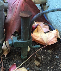
A metal stake driven into the ground next to a home. The wire clamped to the stake curves up to the right to provide the safety ground reference for the home’s electrical system. Sometimes the grounding wire is clamped to a water pipe where the pipe disappears into the Earth.
Ground is
- the reference point from which voltages are measured,
- the return path carrying electric current back to its source,
- a direct physical connection to the Earth, for safety.
safety ground
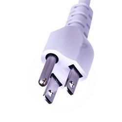
Any electric device plugged into the wall has very high voltages inside $(110\,\text V$ or $220\,\text V)$. If something inside the device fails the high voltage might touch the metal case. If you touch the device you will get a very dangerous shock.
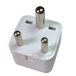
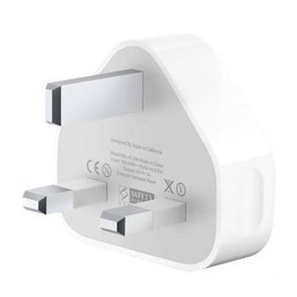
For safety, devices have a feature to direct the dangerous current into the Earth rather than through you. A grounding wire connects the metal enclosure to a safety ground wire in the power cord. That’s why there’s a third prong on a power plug.
The safety ground wire goes through the home’s electrical system and out to Earth, as shown in the leafy photograph above.
The moment a fault happens the dangerous current is guided to Earth and away from people. The high current is sensed by the circuit breaker or fuse, which opens up to remove power from the faulty device. When the device is working properly, no current flows in the safety ground wire.
Ground gets its name from the third meaning, but all three roles are equally important.
You will come across various symbols for ground. They all indicate which node is the reference node.

Summary
We now have a full vocabulary for talking about circuits and their sub-parts.