Real-world circuit elements
The circuit elements discussed in the previous article are ideal circuit elements. Real-world circuit elements come close to the ideal mathematical models, but inevitably will be imperfect. Being a good engineer means being aware of the limitations of real-world components compared to their the ideal abstractions.
Written by Willy McAllister.
Contents
Real circuit elements are not ideal
Real-world circuit elements are never ideal. We will go through several examples where a real device does not perfectly behave like the corresponding ideal mathematical model. Note: This article seems like it’s filled with a lot of bad news about non-ideal features of components. But there’s no need to get overwhelmed. In the electrical engineering subjects covered here, you won’t have to worry about parasitic effects. I talk about them so you know they exist.
Tolerance
Device parameters like $(\text{R, L, and C})$ are never exactly the specified values. There is always some variation or tolerance around the advertised value. You can buy components with tight tolerance, if you are willing to pay more money). Your designs need to allow for tolerances on device parameters, since they are inevitable. This is one of the engineering skills you will get really good at.
Extreme current and voltage
Another way real elements deviate from their ideal equations when current or voltage are taken to extreme values. For example, the Ohm’s Law model of a resistor is a straight line stretching out forever. But for real resistors, the current and voltage can’t go to $\infty$. At some point, the model breaks down and the resistor no longer obeys Ohm’s Law (because it burns up).
Parasitics
Real components are always more than just their component name. I’ll use a resistor as an example. A real resistor’s connecting wires have current flowing in them, which generate a surrounding magnetic field. That means the resistor inevitably displays the properties of a small inductor. Also, resistors are usually located near other conductors. Together these conductors act like the plates of a capacitor with an electric field between them. So resistors display the properties of a small capacitor.
These extra properties are called parasitic effects. These tiny inductors and capacitors are important if they the circuit works different than you expect. Parasitics have their largest effect when the frequency is high, or any time there are sharp changes to voltage or current.
Most of the time we can ignore these parasitic effects, until we can’t. That’s an odd way of saying that you will use your judgment and experience to decide if parasitics need to be accounted for. If parasitics matter, you can model a component as a combination of ideal elements, as shown here for a resistor. The resistor symbol is the intended component, and the capacitor and inductor represent parasitic effects.

Temperature sensitivity
The properties of real-world components are sensitive to their environment. Most components show some degree of temperature sensitivity; parameters drift high or low depending on how hot or cold the component is. If your circuit has to work over a wide temperature range, you will want to know the temperature behavior of the components you use.
Resistors have some degree of temperature sensitivity. Sometimes we build thermometers based on a resistor’s sensitivity to temperature. Inductors and capacitors are relatively insensitive to temperature. The components with the greatest sensitivity are semiconductor devices: transistors and diodes. These actually include temperature, $T$ in their $i$-$v$ equations.
Real-world resistors
When making real resistors, the goal is to create a component that comes as close as possible to performing like Ohm’s Law, the ideal resistor equation,
$v = i\,\text R$
The two symbols for a resistor look like this,

In the US and Japan the resistor symbol is a zig-zag. In the UK, Europe and other parts of the world, the resistor is drawn as a box.
Resistor properties
The resistance value of a resistor depends on two things: what it is made of, and how it is shaped. The bulk material properties determine how difficult it is for electrons flow through. You could think of it as how often electrons crash into the atoms in the material as they try to flow by. This property of a bulk material is called resistivity. You might also hear about conductivity, which is just the inverse of resistivity.
After selecting a bulk material with a certain resistivity, the resistance of the resistor is determined by its shape, typically a cylinder, or long rectangle, or ribbon. A longer resistor has higher resistance than a shorter resistor. Electrons suffer more collisions as they pass through the jungle of atoms in the material. A resistor with a bigger cross-section (a fatter cylinder) has lower resistance than a resistor with smaller cross-section, because electrons have a greater number of available paths to follow.
There are lots of “R” words. A quick summary,
- Resistor is a circuit element, a physical object with a manufactured shape.
- Resistivity is a property of a bulk material. The unit of resistivity is ohm meters, $\Omega \cdot \text m$.
- Resistance is property of a resistor, determined by both the resistivity of the material and the shape of the resistor. The unit of resistance is ohms, $\Omega$.
A real resistor breaks down (burned up, destroyed) if the heat dissipated by the resistor is greater than what its construction materials can stand. Resistors come with a power rating that you should not exceed in your design. If you try to dissipate $1$ watt in a $1/8$ watt resistor, you may end up with a burned chunk of something that is no longer a resistor.
Axial resistors
Example of a conventional axial resistor,
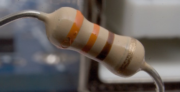
The color bands tell you the value of the resistor and its tolerance. The bands on this resistor are Orange Orange Brown Gold. From the resistor color code chart, the first two bands corresponds to the digits of the value, $3\, 3$. The third band is the multiplier, brown stands for $\times 10^1$. The fourth (last) band indicates the tolerance, gold is $\pm 5\%$. The resistor value is $330 \,\Omega\,\pm5\%$.
resistor color code

This is a precision resistor with 5 color bands,
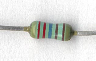
Read the bands from left to right: Red Red Blue Brown Brown $= 2 \,2 \,6 \,1 \,1$. The first three bands $(2\,2\,6)$ are the value. The fourth band is the multiplier $(\times 10^1)$. The fifth (last) band indicates the tolerance. A brown band is $1\%$. (If you ever come across a red band it stands for a tolerance of $2\%$). The resistor value is $2260 \,\Omega\,\pm 1\%$.
Reading this resistor value is pretty tricky. It is hard to tell which end you start at. If you look very closely, the gap between the two brown bands is slightly larger than the other gaps. That tells you the last brown band is the tolerance. When in doubt, use an ohmmeter.
Surface mount resistors
This is a surface mount resistor,

The resistance value is encoded in the $3$-digit code: $102$, meaning $10 \times 10^2 = 1000 \,\Omega$. You can’t tell from the picture but the size of this resistor happens to be “0602”, indicating its footprint is $6 \, \text{mm} \times 2 \, \text{mm}$.
Here’s how a surface mount resistor is made. The resistor itself is a single layer of material screened on top of a little chunk of ceramic insulator, and covered with a protective layer.

Example of a resistor that’s part of an integrated circuit,

The designer selects one of the layers on the integrated circuit with high resistivity and creates (draws) a serpentine pattern to achieve the desired resistance.
Real-world capacitors
When making real capacitors, the goal is to create a component that comes as close as possible to the ideal capacitor equation,
$i = \text C \,\dfrac{dv}{dt}$
The some symbols for a capacitor look like this,

The version with the curved line is used for capacitors that require one terminal to have a positive voltage with respect to the other terminal (“electrolytic” capacitors). The curved line indicates the terminal that needs to be kept at the more negative voltage.
We make capacitors from two metal surfaces placed close to each other but not touching. Between the plates there can be air or some other kind of insulating material. The capacitance of the structure depends the area of the plates, the distance between the plates (the thickness of the insulator), and the physical properties of the insulating material.
Learn more about capacitors and how they work in the capacitors and capacitance section in Khan Academy Physics.
Real capacitors come in lots of different shapes,
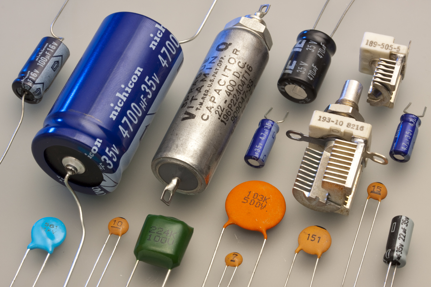
Cylindrical capacitors (upper left, black, dark blue, or silver) are made of two metal foil plates rolled up like a jellyroll to pack a large plate area in a small space. The circle-shaped capacitors (bottom, aqua and orange) are simply two metal disks facing each other, separated by an insulator. Adjustable capacitors (right, white and metal) use air as the insulator between plates. One set of plates rotates, changing the overlapping area with the stationary plates to change the capacitance. Variable capacitors are used to tune radios, for example.
Breakdown
For real-world capacitors the most likely departure from the ideal capacitor equation happens if the voltage across the capacitor becomes so large the insulation between the plates breaks down. When this happens, a spark can burn through the insulation. No more capacitor. Real capacitors have a voltage rating that should not be exceeded.
Parasitics
Since a capacitor has connection wires, it inevitably has a small parasitic resistance and inductance. The parasitic inductance can be important if the capacitor is expected to provide sudden bursts of current, such as when it is connected to the power pin of a digital chip. This parasitic inductance may be big enough to matter if you build very fast digital circuits.
Leakage
The material separating the capacitor plates is supposed to be insulating (allow zero current). But not all insulators are perfect, so tiny currents can seep through. These leakage currents flow straight through the capacitor, even if the voltage is not changing (when $\text dv/\text dt = 0)$. It seems like there’s a large-value resistor in parallel with the capacitor. Leakage paths also happen if the circuit is not clean. Leakage current can flow around the capacitor, along the surface of the component.
A surface mount capacitor is shown here,
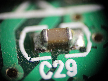
Leakage currents might flow between the metal ends of the capacitor through the gunk left behind from the soldering process if the circuit board is not cleaned very well.
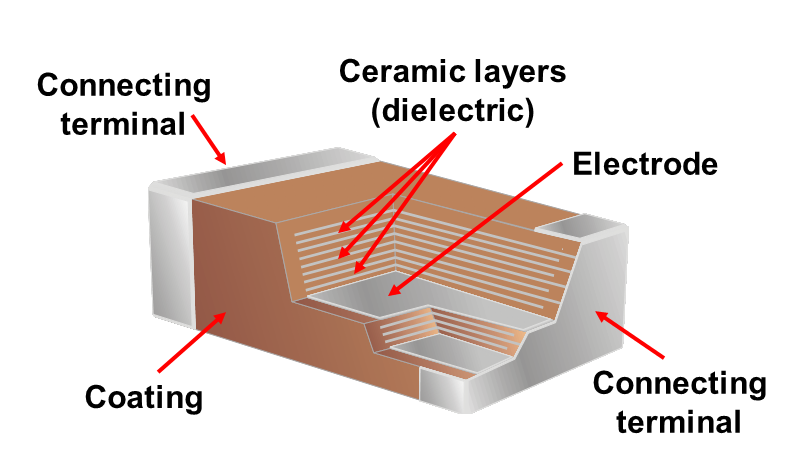
Here’s a peek inside a surface-mount capacitor. It is a stack of many layers of interleaved conducting plates and insulating ceramic layers.
Real-world inductors
The theory of how an inductor works is actually pretty complicated. To learn more about inductors and magnetic fields, see the magnetic fields section of Khan Academy Physics.
When you make an inductor the goal is to come as close as possible to the ideal inductor equation,
$v = \text L \,\dfrac{di}{dt}$
The symbol for an inductor looks like this,

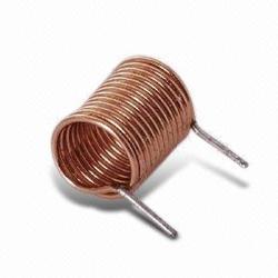
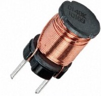
It looks like a wire wrapped around in a coil, since that is the usual way to make an inductor.
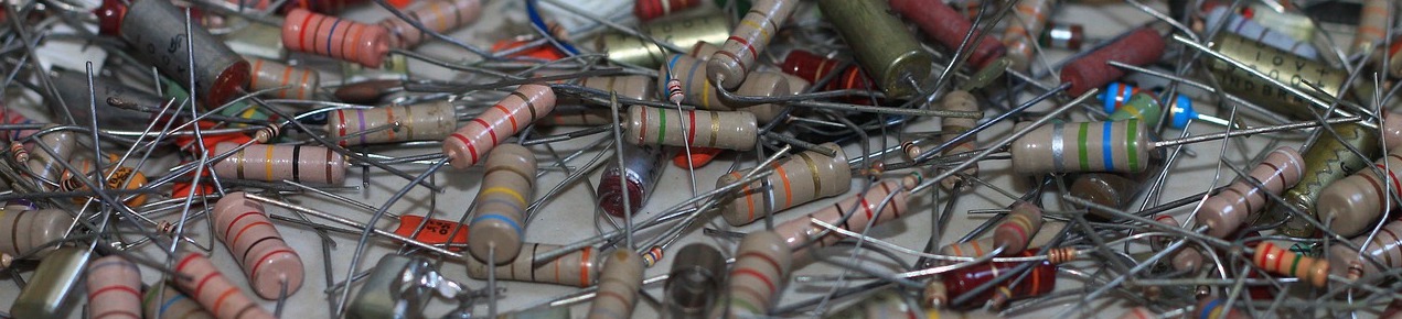
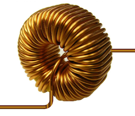
Real-world inductors come in lots of shapes.
Parasitics
Real inductors differ from the ideal equation in one important way. Since inductors are made of long wires, they often have a significant parasitic resistance. This extra resistance is the main parasitic of an inductor.
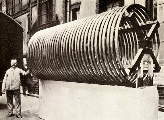
The other unavoidable feature of inductors is they take up a lot of space. The magnetic field exists in the volume of space around and inside the inductor. The coil of wire has to be big enough to surround a large amount of magnetic field to achieve a significant inductance. It is rare to see an inductor designed into an integrated circuit.
We finish up with this astonishing image of an air-core inductor. This large copper coil was part of a wireless telegraph station built in New Jersey, USA in 1912. It could send a message 4000 miles (6400 km), all the way across the Atlantic Ocean to Germany. Wow. Needless to say, most inductors are much smaller.