Assertion
Logic signals are usually described as TRUE or FALSE, 1 or 0. There are several other ways to describe signals,
- high or low
- active high or active low
- on or off
- asserted or not asserted
Each term gives you a slightly different perspective when reading logic diagrams.
Written by Willy McAllister.
Contents
We can build up an interesting and flexible vocabulary for logic signals. This isn’t a new digital theory, but rather a perspective that enriches your understanding of digital logic.
We work with two signals, RESET and SET.
TRUE/FALSE 1/0
The usual way to talk about logic is to allow two possible values, TRUE or FALSE. These can be abbreviated T and F, or 1 and 0. When we use 1 and 0 this way they are not being used as numbers, but rather as two distinct symbols that are easy to tell apart at a glance. (Later on when we study binary arithmetic we will use 1 and 0 as numbers.)
Our two signals, RESET and SET, can take on two logical values, T/F or 1/0.
High and low
When we build logic in hardware logic values are usually represented as two distinct voltage levels. The voltage levels are always a range of values. For example, in a 3.3V CMOS logic family,
logic 0 is anywhere in the range 0V - 0.8V
logic 1 is anywhere in the range 2V - 2.4V
This is what logic 1 and 0 look like on a voltmeter or oscilloscope, and it suggests another way to name the logic levels — HIGH and LOW,
HIGH is TRUE or 1 because in digital hardware the higher voltage is associated with the logic 1 state.
LOW is FALSE or 0 because the 0 logic state in hardware is represented by the lower voltage, usually close to 0 volts.
When we associate HIGH with TRUE/1 it is called positive logic.
negative logic
In the early days of the digital age some logic families implemented negative logic. PMOS and ECL (emitter-coupled logic) families used the opposite association where logical 0 was near 0 volts and logical 1 was a lower voltage. These technologies are obsolete so it’s unlikely you will ever deal with negative logic.
Active high, active low
Here’s another way to talk about logic values. We say signals are active. Let’s explain with our two example signals,
When RESET is HIGH it wants to reset whatever it is connected to. When RESET is LOW it means, “I’m not telling you to reset, so do whatever you are supposed to do.” We say RESET is active high. Active means the signal is saying, “do what my name says.”
When SET is LOW it wants to set something. When SET is HIGH it means, “I’m not telling you to set, so do whatever else you are supposed to do.” We say SET is active low. Active means the same thing it means for RESET, it means “do what my name says.”
How do you tell if a signal is active high or low? If it does not have a negation symbol—no bar or other negation indicator—it is active high. If it is negated, it’s active low. It doesn’t matter what the signal name is. The signal name represents “this is what I do.”
It is important to pick good signal names. Pick names that mean “this is what I do.”
On and off
We can also talk about logic signals being ON or OFF. ON and OFF don’t mean the same as 1 and 0, or TRUE and FALSE, or high and low. Let’s illustrate with a light switch,
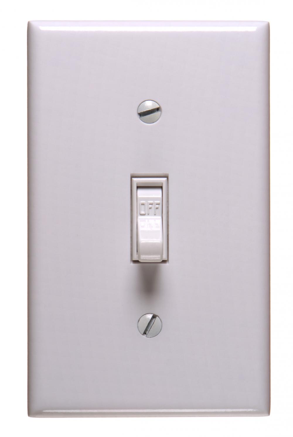
A normal light switch is mounted so the light is ON when the lever is up.
ON turns the light on. With the switch mounted in it’s usual orientation, it seems okay to associate ON with 1/TRUE/HIGH.
But, what if I remove the light switch from the wall and reinstall it upside down? What happens? Flipping the switch to ON still turns the light on, but it the switch is flipped down. It doesn’t make sense to associate ON with 1/TRUE/HIGH any more. ON is now 0 or FALSE or LOW. And 1/TRUE/HIGH now means OFF! What the heck is going on here?
It’s kind of tricky. Here’s where the confusion comes from. ON is associated with the light bulb, not with how the switch is installed. ON represents our intent for what the light bulb should do. ON has nothing to do with how the switch is mounted on the wall.
ON corresponds to “do what my name says.” It is the active state of the switch. If our light switch is installed upside down, ON is active low. If we turned the switch around the normal way, ON becomes active high.
Assertion
Now we come to the idea of assertion. When a signal is asserted that means it is active, it is doing what its name says. You use assertion to describe the state of both active high and active low signals.
RESET is asserted when it is active, which is HIGH.
SET is asserted when it is active, which is LOW.
The opposite of asserted is unasserted or deasserted or not asserted. These are a clumsy words, so try to talk your way around them. “RESET = 0. Is RESET asserted?”, “No, it is not.”
Assertion and gate symbols
Assertion is an alternate way to view gates. When we first defined gates we did it with a truth table of 1’s and 0’s. AND and NAND had different truth tables because one has a bubble and the other does not.
Assertion is a slightly different perspective from 1’s and 0’s. We split the definition of a gate into,
- a distinctive shape
- bubbles to indicate assertion
You already know the distinctive gate shapes,

The distinctive shapes: buffer, AND, OR, and XOR.
First, the shape tells you what the gate does when its inputs are asserted. The shape does its thing and asserts its output,
- The buffer asserts its output if its input is asserted.
- AND asserts its output when both of its inputs are asserted.
- OR asserts its output when either of its inputs are asserted.
- XOR asserts its output when either (but not both) of its inputs are asserted.
Then the bubbles tell you what asserted means,
- If there is no bubble, asserted means HIGH/TRUE/1.
- If there is a bubble, asserted means LOW/FALSE/0.
Gate symbols are a combination of a distinctive shape and some bubbles.
This is an AND gate,

The symbol shape is distinctly AND. That’s “what it does.” An AND gate asserts its output when both of its inputs are asserted.
For an AND gate there are no bubbles, so an input is asserted when high. When the AND gate asserts its output, it drives it high.
This is a NAND gate,

The symbol shape is distinctly AND. That’s “what it does.” NAND has the same logic description as AND: It asserts its output when both inputs are asserted.
NAND has no bubbles on its inputs and a bubble on its output. It considers each input asserted when HIGH, and if it asserts its output, the bubble tells us it drives it LOW.
This is the DeMorgan equivalent symbol for NOR,

The symbol shape is distinctly AND. That’s “what it does.” It has the same logic description as AND: It asserts its output when both inputs are asserted.
This gate has two bubbles on its inputs and no bubble on its output. It considers each input asserted when LOW, and it asserts its output HIGH (because there’s no bubble on the output).
And here’s the final AND shape, the DeMorgan equivalent symbol for OR,

The symbol shape is distinctly AND. That’s “what it does.” It has the same logic description as AND: It asserts its output when both inputs are asserted.
This gate has two bubbles on its inputs and a bubble on its output. It considers each input asserted when LOW, and it asserts its output LOW (because there’s a bubble on the output).
The assertion perspective means the description of all four of these AND-ish gates represent the same idea. It’s remarkably coherent. That’s cool. Thinking about gates like this means you don’t have to rummage through your memory to pull out the truth tables.
It works for the other gates, too.
Here are all the gates with an OR shape,

OR gates assert their outputs when either input is asserted.
And remember all those symbols based on XOR? They are all share the XOR shape, sprinkled with bubbles,

The output is asserted when either (but not both) inputs are asserted.
Oh, and I don’t want to forget the family of buffer/inverter symbols,

By now you should see how these are all similar when described by assertion.