Capacitor i-v equation in action
The capacitor is one of the ideal circuit elements. Let’s put the capacitor $i$-$v$ equation to work to see what happens to the voltage if we put in a current.
Written by Willy McAllister.
Contents
Where we’re headed
A constant current driven into a capacitor creates a voltage with a straight ramp. This behavior is predicted by the integral form of the capacitor $i$-$v$ equation.
The usual capacitor $i$-$v$ equation is $i$ as a function of $v$ in derivative form,
$i = \text C \,\dfrac{dv}{dt}$
$\text C$ is the capacitance, a physical property of the capacitor. $\text C$ is a scale factor, it tells you how much $i$ you get for a given amount of $dv/dt$.
You can write the capacitor $i$-$v$ equation the other way around, with $v$ as a function of $i$. It turns into an equation with a definite integral,
$\displaystyle v = \dfrac1{\text C}\, \int_{\,0}^{\,T} i\,dt + v_0$
$v_0$ is the voltage across the capacitor at the beginning of the integral, at $t=0$.
The notation for time is a bit tricky,
Little $t$ is the continuous time variable inside the integral.
Big $T$ is the moment you want to know the voltage on the capacitor. $T$ is the upper limit of the integral.
calculus notation: $di/dt$
$i = \text C\,\dfrac{dv}{dt}$
$d$ is calculus notation for ‘differential’, or “a tiny change in …”. For example, $dt$ means ‘a tiny change in time’. When you see it in a ratio, like $dv/dt$, that means, “a tiny change in $v$ (voltage) for each tiny change in $t$ (time)” An expression like $dv/dt$ is a derivative. The derivative measures how fast voltage changes with time (the slope of voltage vs. time).
calculus notation: $\int$
$\displaystyle v = \dfrac{1}{\text C}\, \int_{\,0}^{\,T} i\,dt + v_0$
The loopy $\int$ is another symbol from calculus. It is the integral sign. It’s meaning is similar to the summation symbol Sigma $\Sigma$. Integration is the opposite of taking a derivative.
In the capacitor equation, the integral sign means you add up a sequence of products $(i \times dt)$ or (current $\times$ a tiny interval of time). When you see upper and lower limits on the integral symbol that makes it a definite integral. It means to integrate over a specific range of $t$. You start at time $t=0$ and stop at time $t=T$.
Voltage response to a current pulse
In this article we’ll work with the integral form of the capacitor equation. So we know $i$ and we want to find $v$. Our example circuit is a current source connected to a $1\,\mu\text F$ capacitor,

Suppose we apply a $2 \text{ mA}$ pulse of current to the $1 \,\mu\text F$ capacitor. The pulse lasts $3\,\text{msec}$, $(3 \times 10^{-3}$ seconds$)$. The initial voltage across the capacitor is zero.

If the capacitor current looks like this, what does the voltage look like?
Find the capacitor voltage, $v(t)$
To find voltage in terms of current, we use the integral form of the capacitor equation.
$\displaystyle v(T) = \dfrac1{\text C}\, \int_{\,0}^{\,T} i\,dt + v_0$
The current pulse has abrupt changes, so we’re going to solve for $v(t)$ in three separate chunks: before, during, and after the current pulse.
Before the pulse
Before the current pulse $(t < 0)$, no current is flowing, so no charge accumulates on $\text C$. Therefore, $v_{(t<0)} = 0$. We didn’t even have to use the equation.
During the pulse
For any time during the current pulse $(0 \lt t \lt 3\,\text{ms})$, current flows, charge accumulates on $\text C$, and the voltage rises. Apply the capacitor equation to find what happens to the voltage,
$\displaystyle v(T) = \dfrac1{\text C}\, \int_{\,0}^{\,T} i\,dt + v_0$
Pay attention to the time variables. Little $t$ is continuous time, the variable that gets integrated. Big $T$ is the amount of time charge is allowed to accumulate. The definite integral sweeps time $t$ from $0$ up to some accumulation time, big $T$. To find the voltage at the end of the pulse we set big $T$ to $3\,\text{ms}$.
$i$ is constant (the top of the pulse is flat) during this time so we can take it outside the integral. We said the capacitor started with $0$ charge, so $v_0$ is zero and we can leave it out.
$\displaystyle v(T) = \dfrac{i}{\text C}\, \int_{\,0}^{\,T} dt$
$\displaystyle v(T) = \dfrac{i}{\text C}\,\, t\,\bigg |_{\,0}^{\,T}$
$v(T) = \dfrac{i}{\text C} \,T$
This tells us $v$ is a function of pulse duration $T$ and pulse height $i$. The equation has the shape of a line. The slope of the line is $i/\text C$,
$\dfrac{i}{\text C} =\dfrac{2\times 10^{-3}\,\text A}{1 \times 10^{-6}\,\text F} = 2000\,\text{volts/second}$
For any pulse width, the voltage is,
$v(T) = 2000 \,\text{volts/s} \,\cdot T$
Our pulse width is $T = 3\,\text{ms}$, so the voltage across the capacitor rises to,
$v_{(T=3\,\text{ms})} = 2000 \,\text{volts/sec} \,\cdot \,0.003 \,\text{sec} = 6\,\text{volts}$
With a constant current of $2\,\text{mA}$, the voltage on the capacitor rises in a straight line with a slope of $2000 \,\text{volts/sec}$. The voltage started at $0\,\text V$ and rises to $6\,\text{volts}$ after $3\,\text{ms}$.
After the pulse
This part is rather interesting if you haven’t thought about it before. After the pulse the current falls to $0$. That means charge stops accumulating on the capacitor. This may seem weird but since no charge is moving the charge that’s accumulated on the capacitor has no place to go, so it stays on the capacitor. That means we should expect the capacitor voltage to stay the same. $q = \text C\,v$. Constant $q$ implies constant $v$.
See how the math captures this by writing the capacitor equation after the pulse is over.
The starting time is $3\,\text{ms}$. The current is $i=0$ since the pulse is over. The starting voltage is $v_{3\,\text{ms}} = 6 \,\text V$.
$\displaystyle v(T) = \dfrac1{\text C}\, \int_{\,3\,\text{ms}}^{\,T} 0\,dt + 6$
The integral evaluates to $0$ and we get,
$v(T) = 6\,\text V\quad$ for any value of $T$.
Once the current stops, the charge stays put, so the capacitor voltage remains constant at $6\,\text V$. It stays there forever.
Total response
Assembling the three chunks together gives us $v(t)$ in the lower graph,

This circuit configuration (a current source driving a capacitor) has a nickname. It is called an integrator because it accumulates or integrates charge over time. It is often used to generate a ramp-shaped voltage.
Simulation model
Find the current and voltage with this simulation model. Open the link and click on TRAN in the upper menu bar to perform a transient simulation. The current source is modeled as a single PULSE. (Double-click on the current source to see how it is defined.) The zoom controls are on the left side of the window, in light gray.
Design challenge
Here’s another simulation model with the current source defined a different way, as a PWL (piece-wise-linear) waveform. The time and current are entered as a list of comma-separated [time, current] pairs, like this: -1s,0,0s,0,1ns,2m,3ms,2m,3ms,0,5s,0.
See if you can modify the current waveform to get the capacitor voltage to ramp down to $0\text V$ in another $3\,\text{ms}$. You are going for something that looks like this,
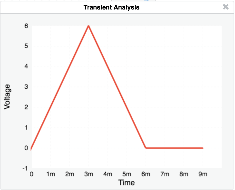
show answer
Double-click on the current source and enter this in the PWL "comma-separated list of alternating times and values".
-1s,0,0s,0,1ns,2m,3ms,2m,3ms,-2m,6ms,-2m,6ms,0,10s,0
The current source pours charge into the capacitor for $3\,\text{ms}$ and the voltage ramps up. Then it reverses direction to pull out charge for another $3\,\text{ms}$. The voltage is another ramp, this time with negative slope since charge is removed.
Summary
If you drive a constant current into a capacitor it produces a voltage shaped like a straight ramp. We used the integral form of the capacitor $i$-$v$ equation to predict this.
The approach to solving this circuit is a good example of how engineers divide a problem up into small bits and pieces, solving each simple piece, and reassembling the complete answer. Your first instinct when faced with a complicated problem like this should be, “How can I chop this up into pieces?”