Circuit sandbox
A simulator for learning about circuits. Circuit Sandbox includes schematic capture and a circuit simulation engine. The circuit simulation engine is written entirely in JavaScript—it is not a version of SPICE.
 Circuit Sandbox simulator, available in
| English | Español | Português | Français | Italian |
| Magyarul (Hungarian) |
हिन्दी (Hindi) |
日本語 (Japanese) |
简体中文 (Chinese) |
Čeština (Czech) |
Can you help translate Circuit Sandbox into other languages? It’s easy!
YOU DON’T NEED TO READ THE REST OF THIS UNLESS YOU GET STUCK.
Contents
- Playing in the sandbox
- Getting started
- Help
- Labeling and annotation
- On-screen controls
- Menu bar
- Device models
- System information
- Configure
- Translation
- The Circuit Sandbox was created at MIT
- Other circuit simulators
- Licensing
- Libraries
Playing in the sandbox
To create a circuit, drag components from the part bin on the right onto the schematic.
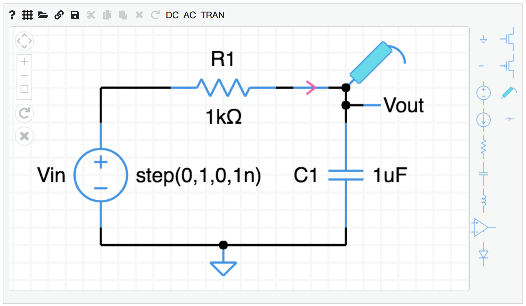
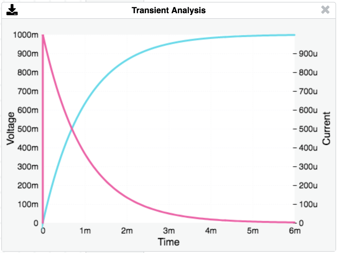
Sample output: Click on TRAN to perform a transient analysis, a plot of voltage vs. time.
Getting started
Drag components from the parts bin onto the main screen.
Add wires by dragging between components connection points (small circles).
Tap on the Rotate icon or type “r” on the keyboard to rotate a component.
Tap on the Delete icon or type BACKSPACE to delete a component.
Double-tap on a component to change its properties, like resistance value.
Add a ground symbol (triangle shape at the top of the part bin).
Add node labels (the short straight line underneath the ground symbol).
Add voltage or current probes to the nodes you want to plot.
Select DC, AC, or TRAN from the menu to simulate the circuit.
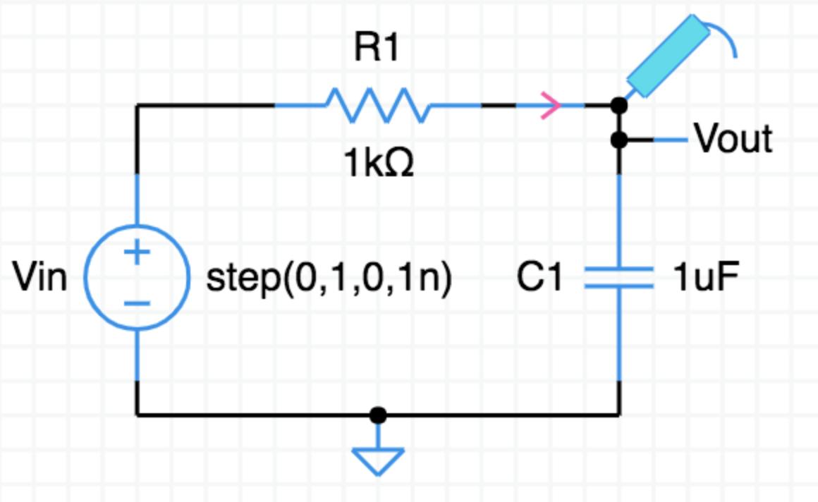
How to build the circuit shown above
To create the $\text{RC}$ circuit shown above, follow these steps starting from a blank schematic (open this link in a new tab).
- Add components (a voltage source, resistor, and capacitor). Click on a component in the parts bin on the right, then click on the schematic. Or, you can mouse down on a component in the bin and drag it to the schematic.
- Select the resistor by clicking on it. It will turn green. While it is selected, hit the “r” key on the keyboard to make it rotate to horizontal. You can also click on the R⤵ icon. Rotate several times to see what happens.
- Position components on the page by dragging them around.
- Add wires by dragging between the connection points on the components. If you make a mistake, hit the backspace/delete key on your keyboard to delete whatever is selected, or click on the $\large \times$ icon.
- Specify a ground node by dragging the ground symbol from the parts bin (the triangle with a stick) and connect it to the bottom of the voltage source.
- Adjust the component properties. Double-click on the voltage source and change its type to “step”. Give it a name if you want. In the same way, change the resistor value to $1$k, and the capacitor value to $1$u. The k and u suffixes are short for $10^{+3}$ and $10^{-6}$.
- Add a voltage probe to the top node of the capacitor. (The thing in the parts bin that looks like a voltmeter probe.) This is the voltage we will plot.
- Select an analysis to perform. For this example, let’s do a transient analysis. Click TRAN in the menu. Set the stop time to $10$m. The m stands for $10^{-3}$ so we will simulate for $10$ milliseconds.
- Click OK. The simulation is performed and a plot should appear.
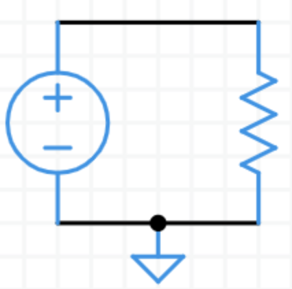
Here is the completed $\underline{\text{RC}}$ circuit.
Help
Add a component: Tap on a part in the parts bin, then tap on the schematic.
Add a wire: Touch on a connection (open circle) to start a wire. Drag. Release.
Select: Tap or drag a rectangle to select components. Shift-click to include another component.
Move: Touch and drag to a new location.
Delete: Select the part(s), then tap or hit backspace/delete on the keyboard.
Rotate/Reflect: Select the part(s), then tap on or hit the keyboard letter “r” to rotate 90. Repeat for more rotations and reflections (8 total).
Properties: Double-tap on a component to change its properties like resistance or voltage.
Scroll/Pan: Tap on-screen scroll/pan arrows, or mouse or trackpad Alt-drag.
Zoom: Tap on-screen zoom controls, or use the mouse scroll wheel or trackpad.
Numbers may be entered using engineering notation,
T    10^12          m   10^-3
G    10^9           u   10^-6
M    10^6           n   10^-9
k    10^3           p   10^-12
                    f   10^-15
example: $1000$ can be entered as $1\text k$
Labeling and annotation
You can give a node a name by attaching the label part—the short straight line under the ground symbol. Double-click on the label and enter a node name.
You can add unattached text annotation to the circuit with the same label part. Place a node label anywhere on the schematic. It does not have to be connected to anything.
On-screen controls
 Scroll/Pan
 Zoom in, out, fit
 Rotate
 Delete
Menu bar
Help: List the Help information shown above.
Grid: Toggle the background grid on and off.
Open netlist: Open a saved netlist.
Shared link: Displays a link you can copy for sharing your circuit. The link is uriencoded, also known as percent encoded. This lets you use these text characters , / ? : @ & = + $ # in signal and component names. The decoded link is echoed to your browser’s javascript console.
Save netlist: Save the current netlist. See System information below for where the circuit gets saved on different platforms.
Cut, Copy, Paste: The usual edit functions.
Mac shortcuts: ⌘-X, ⌘-C, ⌘-V
PC shortcuts: ctl-X, ctl-C, ctl-V
Delete: Delete the selected components.
Simulations
DC: Find the DC voltages and currents, also called the operating point.
AC: Sweep the AC frequency, plot voltage or current vs. frequency.
TRAN: Transient response. Find the time response, plot voltage or current vs. time.
Download: Saves the TRAN or AC data as a .csv file (comma-separated variables) called data.csv in your Downloads folder. This type of file can be opened in Excel or MatLab.
Device models
The simulator has simple models for semiconductor devices (diode, bjt, mosfet) and two operational amplifiers. Each model has just a few adjustable parameters. For more sophisticated simulations, check out the other circuit simulator resources mentioned below.
The simulator’s solver a technique called Modified Nodal Analysis (MNA), based on the application of Kirchhoff’s Current Law. (Whereas the SPICE simulator is based on Kirchhoff’s Voltage Law.)
Diode model
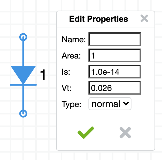
The default saturation current is $\text I_\text s = 1.0\times 10^{-14}$ ampere.
The Area parameter scales the saturation current to Area $\times \,\text I_\text s$.
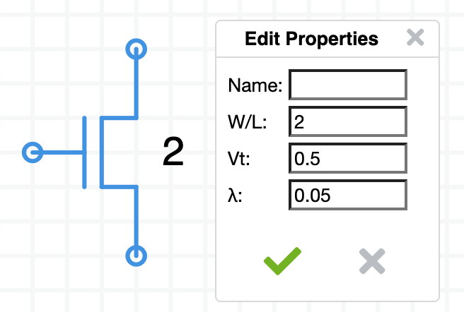
MOSFET model
 $\quad$
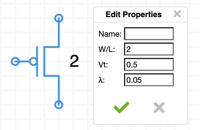
N-type and P-type MOSFETs
The MOSFET model in Circuit Sandbox is the quadratic model. The Linear region is modeled by a quadratic equation, $aV_{DS}^2 + bV_{DS} + c = 0$, described below. Another feature is the parameter ($\lambda$) that models the resistance of the drain-to-source current path.
Fixed parameters
$\mu C_{ox} = 20 \times 10^{-6} \,\text{A/V}^2 = 20\,\mu \text{A/V}^2\quad$ (SPICE parameter KP)
Adjustable parameters
$W/L$ is the area of the device. The default value is $2$.
$V_T$ is the threshold voltage (positive for both N and P types) (SPICE parameter VT0).
The default value is $0.5\,\text V$. When $V_{GS}$ is less than $V_T$ the drain current $I_D$ is $0$.
$\lambda$ is channel-length modulation (SPICE parameter LAMBDA).
The default value is $0.05\,\text V^{-1}$, $1/\lambda = 20\,\text V$. Lambda ($\lambda$) together with $I_D$ determines the small signal output resistance (the upward tilt of the lines in the saturation region),
$r_D = \dfrac{1}{\lambda I_D}\quad$
Cut off region, $V_{GS} \leq V_T$
$I_{D} = 0$
Linear (Non-saturation) region, $V_{GS} > V_T$ and $V_{DS} < (V_{GS} - V_T)$
$I_D = \mu C_{ox} \dfrac{W}{L} \left [ V_{GS} - V_T - \dfrac{V_{DS}}{2}\right] V_{DS} \,(1 + \lambda V_{DS})$
Saturation region, $V_{GS} > V_T$ and $V_{DS} > (V_{GS} - V_T)$
$I_{D} = \mu C_{ox} \dfrac{W}{L} \left [ \dfrac{(V_{GS} - V_T)^2}{2} \right] (1 + \lambda V_{DS})$
Boundary between Linear and Saturation regions
The MOSFET’s behavior changes from Linear and Saturation when $V_{DS} = (V_{GS} - V_T)$. This is the point where the two equations for drain current intersect. That drain current is,
$I_D = \mu C_{ox} \dfrac{W}{L} \dfrac{(V_{DS})^2}{2}\quad$ or $\quad I_D = \mu C_{ox} \dfrac{W}{L} \dfrac{(V_{GS}-V_T)^2}{2}$
This is the rising parabola in the graph.

Here’s the spreadsheet of the MOSFET model equations creating this $I_{D}$ vs $V_{DS}$ plot.
References: Univ Colorado, UC Berkeley
Opamp model
Circuit Sandbox has two opamp models, an ideal model and a realistic model with power supply pins and non-perfect input and output resistance.
Ideal opamp model
The ideal opamp symbol has two inputs ($\sf v$+ and $\sf v$-) and an output ($\sf{vo}$). There are no positive and negative power supply inputs. The extra input, $\sf{vg}$, is the reference for the output voltage.
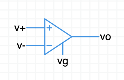
The defining equation for the opamp is: $(\sf{vo} - \sf{vg}) = \text A(\sf v$+ $\,- \,\,\sf v$-$)$
The default gain is $\text A = 30{,}000$. You can change it to anything you want. If the input voltages are identical then the output voltage will be $\sf{vg}$. To simulate symmetric power supply voltages, connect $\sf{vg}$ to ground. To simulate a single-sided power supply (one side is ground, the other is $\text{+Vs}$) set $\sf{vg}$ to $\text{Vs}/2$. It is your responsibility to make sure $\sf{vo}$ stays between the power rails.
Caveats
The MNA simulation model for the ideal op-amp assumes the difference between its two input terminals is zero. It is your responsibility make sure the circuit surrounding the opamp causes this to be true.
The two assumptions for the ideal op-amp (zero input current, zero potential difference at the inputs) only hold if the surrounding circuit is properly configured for negative feedback. The solver may give erroneous results if negative feedback is not present.
The output of the ideal op-amp is not limited by any power supply rail—it will happily generate hundreds of volts on the output.
Realistic opamp model
The realistic opamp model symbol includes power pins,
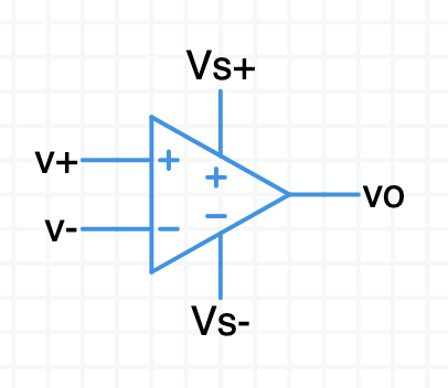
It obeys a similar defining equation: $\sf{vo} = \text A(\sf v$+ $\,- \,\,\sf v$-$)$
More information on this opamp model will appear here soon.
System information
The circuit sandbox works best on a desktop or laptop computer where you have plenty of viewing area. You can also use it on a tablet. (It works on smart phone, too, but the experience is a bit awkward because the screen is so small.) It should work seamlessly in most modern browsers under Windows, Mac, and Linux. If you experience problems, please let me know.
Your circuit is never transferred to the Spinning Numbers web server.
Desktop/laptop
A quick way to save your circuit is to click on the link icon. It displays a big URL you can copy and paste wherever you want. Paste it into a browser to recreate the circuit.
The save icon saves the circuit to the Download folder on your computer in JSON format (JavaScript Object Notation). The file is named ckt.txt.
The open icon loads a circuit from your computer’s file system.
If you want to keep your work be sure to save your circuit before leaving the web page.
Touch devices
If you have a touch device (tablet or smart phone),
- One finger selects a component or drags a selection rectangle
- Two fingers pan the schematic window
Tablet
On a tablet you can save one circuit file. When you save a circuit, it is tucked into a memory area inside your browser. When you open the saved circuit, the circuit file is retrieved from browser memory. If you want to keep your work, be sure to save before leaving the web page.
Mobile devices
The simulator works on a smart phone, but the display is a bit small for drawing schematics. You can save and load one circuit file, the same as for a tablet.
Configure
Circuit Sandbox accepts a few extra parameters to customize the parts bin and analysis choices. You can do this with either the URL or the html <input> statement. Here is an example of a URL with a limited parts bin and analysis choices,
https://spinningnumbers.org/circuit-sandbox/index.html?parts=g,v,r,s&analyses=dc,tran
A URL parameter list starts with a ? question mark. Each parameter is separated by an & ampersand character. Notice there are no quote marks.
You can also provide an initial schematic. Draw up a circuit and grab the URL with the link. The circuit JSON is captured in the value parameter. Append the part and analysis options separated by ampersands,
https://spinningnumbers.org/circuit-sandbox/index.html?value=[["g",[104,112,0],{"_json_":0},["0"]],["r",[128,64,0],{"r":"1","_json_":1},["1","0"]],["v",[80,64,0],{"value":"dc(1)","_json_":2},["1","0"]],["w",[80,64,128,64]],["w",[80,112,104,112]],["w",[128,112,104,112]],["view",0.5,36.5,4,"50",null,null,null,"100","0.01","1000"]]&parts=g,v,r,s&analyses=dc,tran
Circuit Sandbox encodes URL links so they survive trips through email. This same link looks like this when encoded,
https://spinningnumbers.org/circuit-sandbox/index.html?value=%5B%5B%22w%22%2C%5B128%2C112%2C104%2C112%5D%5D%2C%5B%22w%22%2C%5B80%2C112%2C104%2C112%5D%5D%2C%5B%22w%22%2C%5B80%2C64%2C128%2C64%5D%5D%2C%5B%22v%22%2C%5B80%2C64%2C0%5D%2C%7B%22value%22%3A%22dc(1)%22%2C%22_json_%22%3A3%7D%2C%5B%221%22%2C%220%22%5D%5D%2C%5B%22r%22%2C%5B128%2C64%2C0%5D%2C%7B%22r%22%3A%221%22%2C%22_json_%22%3A4%7D%2C%5B%221%22%2C%220%22%5D%5D%2C%5B%22g%22%2C%5B104%2C112%2C0%5D%2C%7B%22_json_%22%3A5%7D%2C%5B%220%22%5D%5D%2C%5B%22view%22%2C0.5%2C36.5%2C4%2Cnull%2Cnull%2Cnull%2Cnull%2C%22100%22%2C%220.01%22%2C%221000%22%5D%5D
You can also initialize a schematic if you call Circuit Sandbox from an html <input> statement—this time with quotes,
<input type="hidden" class="schematic" height="400" width="600" parts="g,v,r,s" analyses="dc,tran" value=[["g",[104,112,0],{"_json_":0},["0"]],["r",[128,64,0],{"r":"1","_json_":1},["1","0"]],["v",[80,64,0],{"value":"dc(1)","_json_":2},["1","0"]],["w",[80,64,128,64]],["w",[80,112,104,112]],["w",[128,112,104,112]],["view",25.5,44,4,null,null,null,null,"100","0.01","1000"]]>
Your choices for analyses are dc, ac, and tran.
Here are your part choices, each part has a one-letter name,
    var parts_map = {
        'g': [Ground, "Ground_connection"],
        'L': [Label, "Node_label"],
        'v': [VSource, "Voltage_source"],
        'i': [ISource, "Current_source"],
        'r': [Resistor, "Resistor"],
        'c': [Capacitor, "Capacitor"],
        'l': [Inductor, "Inductor"],
        'd': [Diode, "Diode"],
        'p': [PFet, "PFet"],
        'n': [NFet, "NFet"],
        'pnp': [PNP, "PNP"],
        'npn': [NPN, "NPN"],
        'o' : [OpAmp, "Op_Amp"],    (ideal)
        'o2': [OpAmp2, "Op_Amp"],   (realistic)
        's' : [Probe, "Voltage_probe"],
        'a' : [Ammeter, "Current_probe"]
    };
Translation
Want to help translate the Circuit Sandbox into other languages? That would be great! If you are fluent in English and another language, especially the technical terms used in the simulator, I could really use your help. Contact me by email and I will provide a table of about 170 terms and phrases for you to translate.
Circuit Sandbox is available in,
- English, en-US.js
- Spanish, es.js (courtesy of Khan Academy volunteer translators)
- Simplified Chinese, zh-cn.js (courtesy of GitHub user Zhu Hao)
- Japanese, ja.js (courtesy of my friend Leslie Shiozaki, a professional translator)
- Hindi, hi.js (courtesy of Aniruddh Pratap Singh, a 12th grade student who wants to become an engineer.)
- Portuguese, pt-BR.js (courtesy of Luís F. V. Peres, graduando em engenharia elétrica de Universidade de São Paulo)
- Hungarian, hu.js (courtesy of Török Attila)
- French, fr.js (contributed by Laurent Defoy, Institute De La Providence Herve, Belgium)
- Italian, it.js (contributed by Paolo Giarrusso)
- Czech, cz.js (contributed by Professor Martin Novák, Czech Technical University in Prague, Czech Republic)
The Circuit Sandbox was created at MIT
The Circuit Sandbox was written in 2011 for MIT 6.002x, the very first massively-open-online class (MOOC). Professor Chris Terman wrote the schematic capture module and Professor Jacob White created the simulation engine based on Modified Nodal Analysis (MNA). MIT transferred Circuit Sandbox to EdX in 2012. I made improvements to the simulator while a Content Fellow at Khan Academy in 2016 and since then.
Circuit Sandbox includes schematic capture and a circuit simulation engine. It is not a version of SPICE. It is its own interpretation of a circuit simulator written in 100% Javascript. It does not require installation—just click on the link and the simulator opens, ready to run.
Other circuit simulators
The granddaddy of all circuit simulation programs is SPICE (Simulation Program with Integrated Circuit Emphasis). This program was created at the University of California, Berkeley in the 1970’s. It was originally written in FORTRAN. SPICE has always been in the public domain. It is one of the jewels of human creativity.
The input to SPICE is a plain-text circuit description (a SPICE netlist). SPICE is the workhorse of the electronics industry because it supports sophisticated models for semiconductor devices (diodes and many types of transistors).
Many people have wrapped front-end interfaces around SPICE to allow designers to draw a schematic and automatically create SPICE netlists. The text netlist is submitted to SPICE for simulation. The results come back and you can plot them. Many of these packages can be found by searching the web for “circuit simulator.”
An excellent version of SPICE is available from Linear Technology, a semiconductor manufacturing company in Milpitas, California. The program is LTSpice (from linear.com) or LTSpice (from analog.com). LTSpice runs on Windows, Macintosh, and Linux machines with Windows emulation. It is free to download and use.
Note: Linear Technologies was purchased by Analog Devices in 2017. The web sites have been merged together.
Another simulator is JADE. It’s a follow-on to Circuit Sandbox with improved features for digital design and logic simulation. Here’s an intro video.
Licensing
© 2017-Present Willy McAllister, © 2012 EdX, © 2011, 2018 MIT EECS
This work is licensed under the Creative Commons (CC BY-NC-SA 4.0) Attribution-NonCommercial-ShareAlike 4.0 International.
Khan Academy makes its software available under the MIT License.
The MIT circuit simulator is part of the EdX Platform, licensed under the GNU AFFERO GENERAL PUBLIC LICENSE Version 3, 19 November 2007. More information at EdX licensing.
Libraries
The Circuit Sandbox simulator uses two open-source libraries,
Download.js is licensed under the Creative Commons Attribution 4.0 International License, attributed to “dandavis”. No changes were made. Download.js allows to circuit files to be downloaded to the client computer.
Hammer.js is available under the MIT License. No changes were made. Hammer.js provides touch functionality, in particular, the double-tap function.
This version of the simulator includes additions by Willy McAllister, including,
- Save/Load netlist
- Sharable link
- Touch sensitivity
- Internationalization
In 2025, Github user Spitfire972 contributed functionality for zooming and panning the schematic canvas.
Questions
How does the voltage probe work ? I dragged, and connected it to various locations, and after clicking the DC simulation button, I did not see any voltage reading from the probe. I looked at the help section, but found nothing. Thanks.
DC simulation doesn’t need a probe. It shows the voltage at every node. The voltage probe is used for AC and TRAN simulations.
I made simple Op amp circuit, and when I click DC analysis I get: Newton method failed. Here is the circuit: Positive of Op Amp is connected to positive of 1V DC. Negative of DC voltage is connected to GND. Negative of Op amp connects to R1=1K, then other side of R1 connects to GND. The negative of Op Amp also connects to Rf=1K which connects to output of Op Amp. I expect Op Amp output = 2V. I advise to fix this bug.
Marzk - I constructed a circuit from your description. DC analysis produces the expected result. Open this link to see the circuit. Please write back if it should be corrected.
Opamp circuit
Thank you Willy. I used the other Op Amp, and neglected to connect the rails. It is working now. But I have suggestion: Instead of having two Op Amp options, make them one, and user double click on it, and enter positive, and negative rail values. After that user does not have to wire them explicitly in the circuit. Right now one of them must be wired explicitly. The other you must wire the GND, but the Hi rail value is unknown.
The two opamp models are ‘ideal” and a more recent addition, “realistic”. The ideal model is used in exercises. It may be replaced over time. The realistic model has exposed power pins you have to connect yourself, which is just what you would have if you retrieve SPICE models from opamp manufacturers. Yes, the schematic is a little more involved, but that’s how it’s done in the real world. You can connect the power pins two ways: by wires to DC sources or connect via wire labels with the same name. Your choice.
How to download it ?
Bibek - The javascript code for Circuit Sandbox can be found in the GitHub repository linked at the bottom of the simulator window. If you just want to run the simulator you don’t need to download it first. Just click one of the links at the top of this Help article.
this is neat
I am thrilled to see your work about internationalization of education. I love to take the of translating this simulation manual in Farsi/Persian language.
Rassoul - Thanks so much for contacting me. The main translation task is to fill out this table of terms used inside the simulator:
https://github.com/willymcallister/circuit-sandbox/blob/gh-pages/Translation-table.docx
Return this to me at willy@spinningnumbers.org. I will create the proper language file, and let you have a chance to check it.
Hello, I am enrolled in edX course that use this simulator, but it seems it doesn´t work, I am using chrome, can you help me please? Thanks
Kevin - Recent versions of Chrome have become picky about some older JavaScript syntax. Perhaps I have not yet discovered all the problem lines. If you know how to work Chrome’s Inspector, see if you can tell me the offending line number in the source code of schematic.js. Or, try any other browser in the meantime while I fix this.
Dear Willy McAllister, Great to see this excellent tool outside of edX. I thought it was brilliant for 6.002x. I hope you don’t mind, but I was just doing a diode i-v plot and noticed that the y-axis scaling is using ‘K’ for kilo. I have to constantly remind students that ‘K’ = Kelvin and ‘k’ =1000 in SI units (ignoring the CS folk who use ‘K’ for 1024!). Great website, fantastic learning resource for would-be electrical engineers. Best wishes.
Ryan - You are exactly right. The engineering notation suffix is now “k” as it should be.
Hello, I am having trouble with this interface, getting connections to work or moving components once dropped (mac, Linux, windows). Also are components moveable once placed? Thank you
Aaron - After you place a component it should move when you click/drag it to a new location. I run Sandbox on a Macbook Pro with either Chrome (v68) or Safari (11.1.2). I checked it on Win10 with Chrome (v67) and Edge (v42) What is your setup? When you click on a placed component does it turn green (selected)?
nise share thank you
this is handy
Thanks. Glad you found the Sandbox useful.
I am trying to simulate an AC-circuit with an AC-Voltage and an AC-Current sources. But the simulation doesn’t deliver the same results as calculated. Is it possible to e-mail you the circuit with the calculated values (as jpg-files)?
I can look at your circuit and calculations. If you drew your circuit in Circuit Sandbox, click on the Link icon in the main menu, copy the entire big URL and mail that along, too, to willy@spinningnumbers.org.