Diode introduction
These small glass packages have silicon diodes inside. The black band at one end is the cathode, the side where current flows out of the diode.
The diode is our first semiconductor device. A diode’s distinctive feature is that it conducts current in one direction but not in the other. We won’t go into the details of how a diode does this or how it’s made. Fortunately, you don’t have to know how to make a diode before you can use it in a circuit.
Written by Willy McAllister.
Contents
- Diode symbol
- Diode terminals
- Types of diodes
- Diode $i$-$v$ characteristic
- Forward bias
- Reverse bias
- Reverse breakdown
Where we’re headed
-
A diode conducts strongly in one direction, and practically $0$ in the other.
-
Learn to identify the terminals of a real-world diode – cathode and anode.
-
Understand diode terms – forward bias, reverse bias, saturation current, and breakdown.
A diode is any electrical device with the property that it conducts in one direction and not in the opposite direction. Every diode you will come across in modern electronics is made with semiconductor material.
What is a semiconductor?
Semiconductor materials fall between insulators and conductors. They semi-conduct. Semiconductors usually act like insulators, but we can control how much they conduct by changing the way they are made – by adding faint amounts of impurity atoms – and by applying voltage.
The most well-known and well-understood semiconductor material is Silicon (Si, atomic number $14$) in the periodic table. Silicon is by far the most common material used for creating semiconductor devices. More is known about silicon than perhaps any other material on Earth.

Part of the periodic table showing silicon (Si) and other nearby semiconductor materials. B - boron, C - carbon, N - nitrogen, Al - aluminum, Si - silicon, P - phosphorus, Ga - gallium, Ge - germanium, As - arsenic.
Other semiconductor materials include germanium (Ge, atomic number $32$, right below Silicon), and gallium-arsenide, a $1 : 1$ ratio of Gallium and Arsenic, also known as GaAs, (atomic numbers $31$ and $33$, on either side of germanium).
Our ability to finely control the conducting properties of silicon allows us to create modern marvels like computers and mobile phones and every other complex electronic device. The details of how a semiconductor works are governed by quantum mechanics.
Diode symbol
The schematic symbol for a diode looks like this,

The black arrow ► in the symbol points in the direction of the diode’s forward current, $\blueD i$. The diode’s voltage, $\goldD v$, is oriented with the $+$ sign on the end where forward current comes into the diode, just like the sign convention for passive components.
Diode terminals
When you draw diodes, the symbol clearly indicates the direction of forward current flow. You usually don’t need names for the two terminals. You will come across them in data sheets, the Anode and Cathode.

How can I remember the anode and cathode?
For the longest time I could not remember which end of the diode was the anode and which was the cathode – I looked it up every time. I finally came up with a memory aid. The German word for cathode is Kathode. The big K kind of looks like a diode symbol.
Flip the diode symbol around until it reads like a K. The Kathode is the terminal on the left.

Identify the terminals of a real-world diode
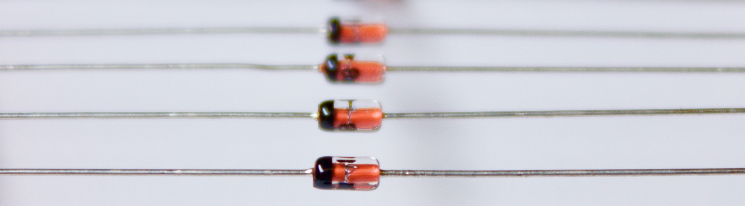
If you are handling real diodes you have to figure out which way to point the diode. Real-world diodes are so small there isn’t room to paint a little diode symbol on them, so you need to identify the terminals some other way.
Diodes come in all sorts of tiny packages. There are a few ways to indicate which diode terminal is which.
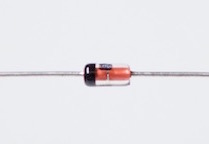
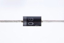
Diode packages like the glass and black plastic cylinders shown above usually have a painted bar near one end. The bar on the package is the bar of the diode symbol, so it indicates the cathode.

The stripe (any contrasting color) corresponds to the diode’s cathode.
This red LED (light emitting diode) does not have a stripe, but instead has wire leads of different length. The forward current goes into the longer lead (anode). The package may have a bump or tab sticking out on the anode side.

The longer lead corresponds to the anode. Current flow into the diode from this direction.
Identify the terminals with a multimeter
A reliable way to verify the identity of the terminals is using a multimeter to figure out the forward current direction. When the meter is set to read resistance, $\Omega$, it puts a small voltage on its test leads (this is why an ohm meter needs a battery). You use that small voltage to see which way current flows.

The diode is flipped in each image.
$\text a.$ If the ohmmeter reads a finite resistance that means the diode is conducting a small current in the forward direction. A small current is flowing from the red $+$ lead through the diode. That means the red lead is touching the anode.
$\text b.$ If the resistance reads O.L (for overload), the diode is not conducting current. That means the red $+$ lead is touching the cathode.
Your meter might have a diode setting – a little diode symbol.
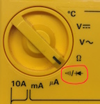
If it does, the meter will display the forward voltage and may beep when the red lead is touching the forward current terminal (the anode).
Types of diodes
There are many types of diodes, differing in materials and processing, and specialized for different uses. Here are a few, (some of these terms haven’t been defined yet)
- Silicon diode – Silicon is the most common material for making diodes. Silicon has a typical forward voltage of $0.6–0.7\,\text V$.
- Germanium diode – Made from a different element. Germanium diodes have a lower forward voltage of $0.25–0.30\,\text V$.
- Schottky diode – Made from direct contact between silicon and metal. The forward voltage is lower than regular silicon diodes, in the range of $0.15$ to $0.45\,\text V$. This is the diode in a “cat whisker” crystal radio.

- Zener diode – Intentionally operated in the breakdown region, used as a voltage reference.

- LED (light-emitting diode) – Does what its name says. Otherwise, it acts like a regular diode with a forward voltage somewhere between $2$ and $4\,\text V$ depending on the color. LEDs are made of materials on either side of Silicon on the periodic table. For example, you can make a yellow LED from gallium arsenide phosphide (GaAsP).
- Photodiode – This diode has a window to let light fall directly on the silicon surface. The current in the diode is proportional to the intensity of light. Solar cells are photodiodes.
- Small signal diode or switching diode – A silicon diode constructed to be very fast changing from forward current to reverse current and back. This is done by making the diode physically very small.
Diode $i$-$v$ characteristic
A diode is a non-linear device. This is a typical $i$-$v$ curve for a silicon diode,

Diode $i$-$v$ curve of a silicon diode. A positive voltage (anode higher than cathode) on the diode puts it in its forward biased region. A negative voltage means the diode is operating in its reverse biased region. At negative voltages exceeding $\text V_{\text{br}}$ the diode is in breakdown and the current rapidly increases in the negative direction.
The blue curve above can be created by measurements. Take an ordinary diode and apply different voltages to it. Write down the current at each voltage. Your $i$-$v$ data will resemble this plot.
Forward bias
Let’s say we place a small positive voltage, like $+0.2$ volts, across a silicon diode. That puts us just a little bit to the right of the origin of the $i$-$v$ curve. With this small positive voltage, very little forward current flows. If we increase the voltage up to around $+0.6\,\text V$ a measurable current starts to flow through the diode in the forward direction (in the direction of the arrow ►). As the voltage moves a little above $0.6\,\text V$, the current through the diode rises rapidly. The $i$-$v$ curve is nearly vertical at this point (it tips a little to the right).
With a positive voltage on its terminals, we say the diode is forward biased. A diode is forward biased when its voltage is anywhere on the $+$voltage side of the origin. In normal operation, the voltage across a forward biased silicon diode is somewhere between $0.60–0.75\,\text V$. If you force the voltage higher than $0.75$ volts, the diode current goes way up and it may overheat.
Reverse bias
If you apply a negative voltage to a diode, so the $-$cathode terminal is higher voltage than the $+$anode terminal, this puts us on the left side of the $i$-$v$ curve. We say the diode is reverse biased. In the reverse direction, the current is very close to zero, just ever so slightly negative.
There is a tiny bit of current that flows when a diode is reverse biased. We call it the reverse saturation current. This current flows in the opposite direction of the arrow ►, from the cathode toward the anode. A well-made diode has a typical reverse current of $10^{-9}$ to $10^{-12}\,\text A$. In most situations, this is close enough to zero to be ignored. In some cases (like an integrated circuit with millions of diodes), the reverse saturation current becomes important and you give it a bad-sounding name: leakage current.
What does "bias" mean?
You hear the word bias in conversations about diodes and transistors. It does not have a single precise definition.
In everyday use, bias can be negative, implying unfairness or favoritism, "The rules are biased against me." Or it might describe a tendency, "They show a bias for taking action." Or "The goalkeeper has a bias for jumping to the left on penalty kicks."
In electronics, bias comes up in only a few situations. It has the sense of pulling to one side. When talking about diodes as we are doing here, forward bias means an applied voltage is tugging the diode toward the forward conducting side of its $i$-$v$ curve. Reverse bias is the opposite, a negative voltage pulls the diode into its reverse bias region where it does not conduct.
The other place you talk about bias: You apply a bias voltage to the terminals of a transistor to place it in a voltage range where it works best. For example, if a transistor works best when its input terminal is between $1$ and $3$ volts, you apply a bias voltage centered at $2$ volts, right in the middle of its happy zone.
Reverse breakdown
A reverse biased diode can’t hold out forever. When the voltage reaches a high negative value known as the breakdown voltage, $\text{V}_{\text{br}}$, the diode starts to conduct in the reverse direction. At breakdown, the current sharply increases and becomes very high in the negative direction. A breakdown voltage $\text{V}_\text{br}$ of $-50\,\text V$ is typical of ordinary diodes. Most of the time you don’t allow the diode voltage to get near $\text{V}_\text{br}$.
Summary
The schematic symbol and terminal names for a diode,
A diode conducts strongly in the direction of the black arrow, and essentially $0$ current can flow in the opposite direction.
A diode made of silicon has a forward voltage between $0.60–0.75\,\text V$.