Forced response
Forced response is not an easy concept. Prominent authors define forced response different ways. I wasn’t aware there was more than one definition until recently—I always thought forced response was what I was taught in school. Then a KA learner pointed out the other definition and threw me for a loop. I decided to review multiple presentations to learn both perspectives, and share what I learned with you.
Written by Willy McAllister.
Contents
Related articles
RC natural response - intuition
RC natural response - derivation
RC step response - intuition
RC step response - derivation
Where we’re headed
- Forced response can be defined two ways.
- If you are talking to someone about forced response and you sense a disconnect it may be because of different electronics backgrounds.
- Not many engineers are aware there are two definitions. Most students don’t buy two expensive textbooks on the same topic, so we never run across the other definition.
- None of this matters for the total response—the one you observe with an oscilloscope—it comes out the same. You can be confident in your answer with either definition.
- What does matter is the process you use to find the forced response.
- There is also a small difference in how the the natural response is defined.
- I prefer one definition over the other, and I will describe why. I use that definition to derive the RC step response.
The total response of an $\text{RC}$ circuit with a step input can be found with different mathematical methods. Once you derive total response you can look back at the journey and give names to parts of the solution. Depending on the method used, the terms natural and forced response can be assigned different ways. The definitions are arbitrary, but can lead to confusion if you are not aware of the different paths to the answer.
Definitions of forced response
Forced response can be defined two ways,
- Forced response is the circuit’s final steady state.
- Forced response is what happens when initial conditions are set to $0$.
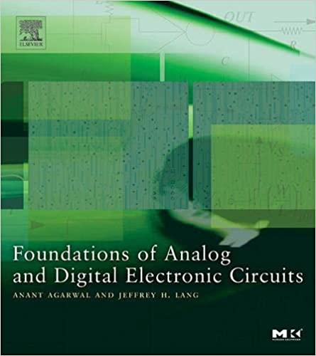
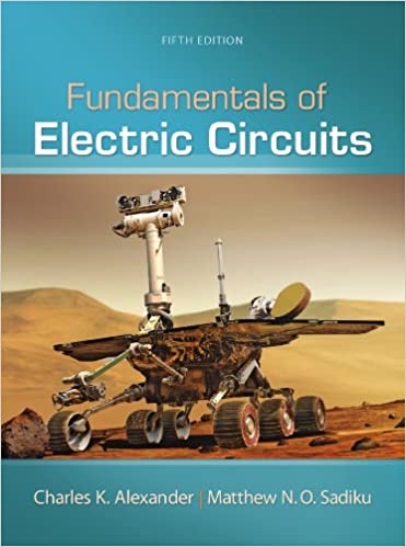
These two relatively modern well-known textbooks have trained many electrical engineers,

Agarwal and Lang, Foundations of Analog and Digital Electronic Circuits, 2005, p. 506.

Alexander and Sadiku, Fundamentals of Electric Circuits, 5th Edition, 2012, p. 275.
They show the two approaches to forced response.
In what follows I assume you are familiar with the natural and step response derivations listed in the references above, so we go through the math quickly.
Agarwal and Lang
Agarwal and Lang derive the step response using the first definition of forced response,
Forced response is the circuit’s final steady state.
This method is based on a theorem of non-homogeneous differential equations,
The total solution to a non-homogeneous differential equation can be found by adding the general solution of the circuit’s natural response to any particular response, followed by applying the initial conditions to resolve unknown constants.
The theorem tells us to find the general form of the natural response (the one with $K_n$ as the arbitrary constant). For the $\text{RC}$ circuit the general natural response is,
$v_n = K_n\,e^{st}$
Then the theorem says we are allowed to find any particular response. We actually search for a very specific particular response, the one that represents the long term steady-state response of the circuit. This particular particular response is pretty easy to find because it looks a lot like the forcing input. We give it the name forced response. The forced response to a step input is the step voltage,
$v_f = \text V_\text S$
The theorem says we add $v_n + v_f$ to get the total response in general form,
$v_{tot} = K_n\,e^{-t/\text{RC}} + \text V_\text S$
We’ve held off applying the initial condition until now. It’s finally time to apply it to the total response (not just the natural response). This resolves $K_n$ and gives us the answer,
$\boxed{v_{tot} = (\text V_0 - \text V_\text S)\,e^{-t/\text{RC}} + \text V_\text S}$
Here’s a plot of the three parts of the solution,
The total response (middle) is the sum of natural plus forced: $\left [(\text V_0 - \text V_\text S)\,e^{-t/\text{RC}}\right ] + \left [\text V_\text S\right ]$
The natural response is a scaled version of the $\text{RC}$ natural response you are used to—the one that starts at $\text V_0$ and ends at $0$. It may look a little goofy hanging down below the time axis, but it’s just scaled/flipped to make the total response blend perfectly between the initial condition and the final voltage.
This is my preferred way to define the forced response. I like the clear distinction between the transient portion and the steady-state portion. This is how the forced response is developed in the $\text{RC}$ step response derivation.
At Khan Academy we would say this is the mathy way to solve the problem. Critics say this gets you to a correct answer but without the physical insight into what is happening. Adherents (like me) say pshaw I can handle that—besides, this method generalizes to non-constant forcing functions like ramps or sine waves.
Alexander and Sadiku
Alexander and Sadiku find the step response three ways. Initially by separation of variables, then by superposition which is described here, and finally by the mathy method shown above. The second definition of forced response emerges from the superposition method,
Forced response is what happens when initial conditions are set to $0$.
We find the step response by the traditional superposition method. The first thing to notice about this circuit is there are two sources of energy: 1. the input source, and 2. energy stored in the capacitor. We break the problem into two simpler sub-circuits. One ignores the input energy and the other ignores the stored energy. Then we superimpose (add) the two individual solutions to get the total solution.
Superposition sub-circuit to find the natural response with the input suppressed.
Superposition sub-circuit to find the forced response with initial condition suppressed.
The natural response sub-circuit has an initial voltage on the capacitor, $v_n(0) = \text V_0$, and the input suppressed (turned off, shorted). We model the circuit with this homogeneous differential equation,
$\dfrac{d}{dt}v_n + \dfrac 1 {\text{RC}} \, v_n = 0$
The solution is the traditional $\text{RC}$ natural response. We find constant $K_n$ using the initial condition. $K_n$ turns out to be $\text V_0$, and the natural response is,
$v_n = \text V_0\,e^{-t/\text{RC}}$
To find the forced response we restore the input source and suppress the initial conditions. This sub-circuit is modeled by the same non-homogeneous equation we developed for the step response, this time with $0$ initial condition,
$\dfrac{d}{dt}v_f + \dfrac{v_f}{\text{RC}} = \dfrac{\text V_\text S}{\text{RC}}\qquad$ with initial condition: $v_f(0) = 0$
This is the original difficult non-homogeneous equation.
Alexander and Sadiku find the total step response with the method of separable differential equations,
$v_{tot} = (\text V_0 - \text V_\text S)\,e^{-t/\text{RC}} + \text V_\text S$
To find something worthy of being called the forced response they replace $\text V_0$ with $0$ to get,
$v_f = -\text V_\text S\,e^{-t/\text{RC}} + \text V_\text S$
$v_f = \text V_\text S\,(1 - e^{-t/\text{RC}})$
The forced response $v_f$ only depends on $\text V_\text S$, there’s no mention of $\text V_0$. This definition the forced response starts at $0$ and includes a steady-state portion and a transient portion.
The total response (which we already know) can be described as the superposition of natural plus forced,
$v_{tot} = v_n + v_f$
$v_{tot} = \text V_0\,e^{-t/\text{RC}} -\text V_\text S\,e^{-t/\text{RC}} + \text V_\text S$
$\boxed{v_{tot} = (\text V_0 - \text V_\text S)\,e^{-t/\text{RC}} + \text V_\text S}$
Here’s a plot of the three parts of the solution,
The total response (top) is the sum of natural plus forced: $v_{tot} = \left [\text V_0\,e^{-t/\text{RC}}\right ] + \left [\text V_\text S\,(1 - e^{-t/\text{RC}})\right ]$
Remarks
In hindsight, I don’t think the superposition method is a very good way to find the step response. You still have to solve the difficult non-homogeneous equation—by separable equations or by introducing an “adjustment factor” (see Ribas below). Neither method generalizes to more complicated forcing functions like time ramps or sinusoidal drive.
The not-very-special case of $\text V_0 = 0$ seems undeserving of a special name like forced response. This is one of the sub-circuits in the superposition method, but the distinction between $\text V_0 = 0$ and $\text V_0 = \text{something else}$ is not noteworthy in the overall result. Hardly seems worthy of a special name.
Summary
The two definitions of forced response arise from grouping the terms of the total response in different ways. The total response is the same either way.
There are three ways to solve the step response,
-
By the method of separable differential equations. This method requires you understand what a separable equation is. It works dandy for the step response, but it does not generalize to other forms of forcing input (ramp or sinusoid). With this method you don’t decompose into natural and forced—you get the total response in one step.
-
By the mathy method of undetermined coefficients where we find and transient response and add it to the steady-state response. The transient response is a scaled version of the conventional natural response. The forced response is defined to be a particular response corresponding to the steady-state response. I prefer this method because it generalizes to other forcing inputs.
| Total response | = | transient response temporary part natural response |
+ | steady-state response permanent part forced response |
- By the method of superposition where we split to the circuit based on the sources of energy, input energy and internal stored energy. The natural response is the familiar one where the exponential dies away to $0$. The forced response is defined to be what the circuit does when the internal stored energy is set to $0$. This forced response has a transient part and a steady-state part. Finding the forced response requires some fancy footwork, either by using the separable equation method or coming up with a “correction” term (see Ribas in References) to find the transient portion. This is not my favorite technique but it is certainly a valid way to think about it.
| Total response | = | stored energy temporary part natural response |
+ | input energy temporary + permanent part forced response |
References
Using separable differential equation to find the RC step response.
Science Direct Forced response is defined as the steady-state response, see Figure 2–6.
MIT Signals and Systems lecture notes — Forced response is the particular steady-state response that resembles the input, see slide 5. See also MIT Transient Analysis of First Order RC and RL circuits lecture notes for a similar definition on page 8.
Stack Exchange question Difference between natural response and forced response?. The forced response is defined as the system’s response to an external stimulus with zero initial conditions. See the detailed answer by Felipe Ribas. He finds the forced response using an “adjustment factor” (an additional exponential term) to “correct” the natural response.
And finally my thanks to Khan Academy learner Cal Colson whose question posted on the KA’s RC Step Response article launched this little research project. This is how I learned about the Ribas essay.