Ideal elements and sources
A circuit is made of elements. Usually at least one element is a source that provides energy to make the circuit do something. The source connects to one or more components that do something useful.
We define sources and components as ideal mathematical abstractions.
The next article is about real-world circuit elements that come close to the ideal versions.
Written by Willy McAllister.
Contents
Start with some definitions,
Elements are sources or components.
Sources provide energy to a circuit. There are two basic types,
- Voltage source
- Current source
Components come in three basic types, each characterized by a different current-voltage relationship,
- Resistor
- Capacitor
- Inductor
These sources and components have two terminals or connection points. Not surprisingly, they are referred to as $2$-terminal elements.
Later on we will learn about components (transistors) that have more than two terminals.
Ideal sources
Constant voltage source
The two common symbols for constant voltage sources look like this,

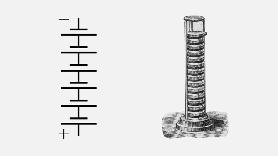
The symbol on the left is a battery. The long horizontal line represents the positive terminal of the battery, and the short horizontal line is the negative terminal. Sometimes the battery is not marked with $+$ and $-$ signs, so this long-line short-line thing is something you want to memorize.
origin of the battery symbol
The battery symbol is a reminder of the very first battery invented by Volta. A stack of alternating dissimilar metal disks,
The circle symbol represents some other kind of voltage source, a power supply or generator. It is best practice to draw the $+$ and $-$ signs inside the circle instead of on the outside. That way they don’t get confused with other voltage labels added to the schematic later.
An ideal constant voltage source has a fixed output voltage, independent of the current,

Current versus voltage plot for a constant voltage source. The current is determined by the components connected to the voltage source.
The $i$-$v$ equation for a constant voltage source is, $v = \text V$, where $\text V$ is some constant voltage, like $v=3\,\text V$. Notice that current isn’t mentioned in the $i$-$v$ equation.
The obvious variable name for a voltage is $v$, but it is also common see the variable $e$ associated with voltage. This comes from the term “electromotive force” or emf. Technically, emf refers to voltage created by a generator, but $e$ is used as a general term for voltage. You can use either $v$ or $e$ and everyone will know what you mean.
$i$ vs. $v$
The plot above is an example of a coordinate system we use a lot. The independent variable on the horizontal axis is voltage, $v$. The dependent variable on the vertical axis is current, $i$. This is called an $i$-$v$ plot.
Variable voltage source
A variable voltage source generates a known voltage as a function of time,

Voltage versus time plot for a variable voltage source.
The defining equation for a variable voltage source is $v = v(t)$. The voltage can be any time-varying voltage. Examples: sine wave, single voltage pulse, or repeating square wave.
more examples of time-varying voltage sources
Step voltage 
Square wave 
Triangle wave 
Sawtooth wave 
The symbol for a variable voltage source looks like this, or some variation,

The squiggle inside the circle suggests a sine wave generator. You will come across different versions of this symbol for other waveform shapes.
If the circuit demands a huge current, an ideal mathematical model of a voltage source provides it. Of course, that doesn’t happen in real life. When you simulate a circuit you might see gigantic currents appear by accident. The computer doesn’t mind a current of a zillion amperes, it’s just a number inside the computer, but it’s probably not what you intended.
Constant current source
The symbol for a constant current source looks like this,

The arrow indicates the direction of current flow.
An ideal constant current source has a fixed output current, independent of the voltage connected to its terminals,

Current versus voltage plot for a constant current source. The voltage is determined by the components connected to the current source.
The equation for a constant current source is, $i = \text I$ where $\text I$ is a constant output current, like $i=2\,\text{mA}$.
Notice there is no mention of voltage in the $i$-$v$ equation. The current is the same no matter what voltage appears across the source. For an ideal current source, the voltage at the terminals is whatever is required to push out the constant current, even if that voltage is gigantic.
When we build real current sources, of course, the range of operation is significantly restricted compared to the ideal current source abstraction.
The idea of a current source is kind of weird, but it is important.
real current sources
A battery has a constant voltage and variable current. That’s why it is a good real-world example of an ideal voltage source. A current source is the opposite, a source of constant current and variable voltage. These are less familiar because you can’t go to the grocery store and buy a current source.
It is possible to build a current source as a rather complicated instrument.
Current sources are used a lot when we model transistors in computer simulation. A region of a transistor’s behavior looks a lot like a current source.
This is a MOSFET transistor symbol,

This is the $i$-$v$ plot of a MOSFET transistor. The horizontal axis is the voltage between the Drain terminal and Source terminal. The vertical axis is the current flowing into the Drain and coming out of the Source. Each blue line represents a different Gate voltage, $\text V_{\text{GS}}$.

Wikipedia article on the MOSFET.
Notice the blue lines to the right of the red curve are horizontal—the area labeled saturation region. In that range of drain voltage the current is constant for any value of $\text V_{\text{DS}}$.
In the saturation region, the MOSFET acts like a current source. We use an ideal current source in the MOSFET simulation model to create that horizontal behavior.

The MOSFET simulation model includes a voltage-controlled current source (the diamond shape). It’s current is determined by a voltage found elsewhere in the model.
Resistor
The two symbols for a resistor look like this,

In the US and Japan the resistor symbol is a zig-zag. In the UK, Europe and other parts of the world, the resistor is drawn as a box.
Ohm’s Law
The voltage across a resistor is directly proportional to the current flowing through it.
$\large v = \text R \, i$
This relationship is known as Ohm’s law. You’ll use this equation a lot in your work with circuits. It’s the most important equation in electronics.
$\text R$ represents the resistance of the resistor. We measure resistance in units of ohms, denoted by the Greek capital Omega symbol, $\Omega$. $\text R$ acts as the constant of proportionality in Ohm’s Law.
Here is the $i$-$v$ plot for a resistor. The line on the plot is Ohm’s Law solved for current,
$i = \dfrac{1}{\text R}\,v\qquad$ The slope of the line is $1/\text R$.

Current versus voltage plot for a resistor.
What is the resistance of this particular resistor?
show answer
We have to figure out the slope of the line. One way to define a line is to find two points. Let’s do that.
The resistor line always goes through the origin, so that gives us one point on the line, $(0, 0)$.
You can pick any other point on the line to find the slope. Look around and pick an easy one. Let’s choose a point in the upper right, $(v = 3\,\text V, i = 4\,\text{mA})$.
So the slope is $\dfrac{4\,\text{mA} - 0}{3\,\text V -0}$.
That means $\text R$ is 1/slope or,
$\text R = \dfrac{3\,\text V}{4\,\text{mA}} = 750 \,\Omega$
It’s possible to write Ohm’s Law a number of ways. You will use all these forms all the time,
$v = i\,\text R \qquad\qquad i = \dfrac{v}{\text R} \qquad\qquad \text R = \dfrac{v}{i}$
remembering Ohm’s Law
Here’s two suggestions for memorizing Ohm’s Law,
The way I memorized Ohm’s Law was to commit one form to memory. I repeated
$e = i\text R \qquad e \, i\,\text R \qquad e \, i\,\text R \qquad e\, i\,\text R \quad…$
until it was embedded in my brain like a mantra. ($e$ and $v$ are both used as symbols for voltage). I happen to like the sound of $e$ in my mantra.)
After uttering my mantra, I quickly derive the other forms with simple mental algebra.
This graphic is another way to remember Ohm’s Law,

Put your finger or thumb over the variable you want $(v$, $i$, or $\text R)$, and read the equation. For example, to find $\text R$, cover up $\text R$ and read $v/i$. To find $v$, cover $v$ and read $i\,\text R$.
Choose a method that works for you to remember Ohm’s Law. It’s worth the effort.
Ohm’s Law is worth committing to memory.
Power in a resistor
Power is dissipated by a resistor when current flows through it.
what is power?
Power
Power is a rate, the rate energy $(U)$ is transformed or transferred.
A physicist defines power in the most general way,
$p = \dfrac{dU}{dt}$
$U$ is energy measured in joules. A joule is the amount of energy expended when a force of one newton is applied over a displacement of one meter.
Power is the rate that energy changes, measured in joules/second.
$1$ joule is also known as $1$ watt.
Electrical power
Electricity carries energy. How can we express $dU/dt$ in more familiar terms?
Voltage is energy transfered per unit of charge, $v = dU/dq$.
Current is the rate of flow of charge, $i = dq/dt$.
We break up $dU/dt$ and express power as,
$p = \dfrac{dU}{dt} = \left (\dfrac{dU}{dq}\right ) \cdot \left (\dfrac{dq}{dt}\right ) = \left (v \right ) \cdot \left (i \right )$
So in electrical systems power is the product of voltage and current,
$p = v \,i $
Energetic electrons moving through resistive material collide with the atoms in the material. The each collision transfers energy from the moving electrons into the material. The collisions cause the atomic lattice to vibrate. That means energy that was in the electrons turns into bulk heat in the resistor material. We can use Ohm’s Law to express power in a resistor two additional ways.
$p = v\,i$
$p = v\,i = (\text i\,\text R)\, i = i^2 \,\text R$
$p = v\,i = v\left (\dfrac{v}{\text R}\right ) = \dfrac{v^2}{\text R}$
The last two expressions reveal that power in a resistor goes up (or down) proportional to the square of current or voltage.
Concept check
-
Increase either voltage or current by a factor of $2$, the power consumed goes up by a factor of $4$.
-
If you reduce either voltage or current by half, how much do you reduce the power?
show answer
Power is proportional to both $v^2$ and to $i^2$. If you cut either voltage or current by a factor of $2$, the power goes down by a factor of $4$.
- Aaron finds a way to reduce the voltage across a resistor by a factor of two. When Beth looks at Aaron’s new design, she figures out how to cut the current in the resistor by a factor of two. After these two design improvements, how much has the power dissipated by the resistor been changed?
show answer
Power in a resistor is proportional to $v^2$, so lowering voltage by a factor of $2$ cuts the power by a factor of $4$.
Power in a resistor is also proportional to $i^2$, so lowering the current by a factor of two also cuts the power by a factor of $4$.
Overall, Aaron and Beth have reduced the power by a factor of $4\times4 = 16$.
Capacitor
The basic equation describing a capacitor relates charge $\text Q$ on the capacitor to the voltage $\text V$ across the capacitor.
$\text Q = \text C\,\text V$
The constant of proportionality $\text C$ is the capacitance. The unit of capacitance is the farad $(\text F)$, and from the equation above we see that, $1 \,\text{farad} = 1 \,\text{coulomb}/\text{volt}$
learn more about Q = CV
Learn how a capacitor is constructed and see how $\text Q = \text C\,\text V$ is derived in this video.
If the charge $\text Q$ is able to move, we have a term for this: moving charge is called current. Current is the time rate of change of charge,
$i = \dfrac{dq}{dt}$
Using this idea that moving charge is current, let’s go back to $\text Q = \text C\,\text V$ and take the derivative of both sides with respect to time and see what we get. (When I start talking about things changing with time, I switch from uppercase variable names to lower case, $q$, $i$, and $v$.)
$\dfrac{dq}{dt} = \text C \, \dfrac{dv}{dt}$
and we end up with an equation saying the current in a capacitor is directly proportional to the time rate of change of the voltage across the capacitor,
$i = \text C \, \dfrac{dv}{dt}$
This equation captures the $i$-$v$ relationship for capacitors. It also tells us that electric circuits can change as time passes.
what does $d$ mean?
The $d$ in $dq/dt$ is notation from calculus. The $d$ stands for differential.
$d$ means “a tiny change in …” The expression $dt$ means a tiny change in time.
When you see $d$ in a ratio, like $dv/dt$, it means, “a tiny change in $v$ (voltage) for each tiny change in $t$ (time).”
An expression like $dv/dt$ is called a derivative. This is what you study in differential calculus.
The some symbols for a capacitor look like this,

The version with the curved line is used for capacitors that require one terminal to have a positive voltage with respect to the other terminal (“electrolytic” capacitors). The curved line indicates the terminal that needs to be kept at the more negative voltage.
We can flip the capacitor equation around to solve for $v$ in terms of $i$ by integrating both sides, resulting in the integral form of the capacitor $i$-$v$ equation,
$\displaystyle v = \dfrac1{\text C}\, \int_{-\infty}^{\,T} i\,dt$
The $-\infty$ lower limit on the integral suggests that the capacitor’s voltage at time $T$ depends not just on the capacitor current right now, but also on the entire past history of the current. That’s a long time ago, so we often write this integral starting at some known voltage $v_0$ at some known time like $t=0$, and then keeping track of the changes from there.
$\int$ is calculus notation
The loopy $\int$ symbol is also from calculus. It is the integral sign. The way it works is similar to the summation symbol $\Sigma$ (uppercase Greek letter sigma).
In the equation above, the integral sign tells you to add up the product of current, $i$, times a tiny interval of time, $dt$, for every $t$ starting at time $t=-\infty$ and stopping at time $t=T$. Integration is the opposite of taking the derivative. You study integrals in integral calculus.
Power and energy in a capacitor
The instantaneous power in watts associated with a capacitor is,
$p = v\,i$
$p = v\,\text C \,\dfrac{dv}{dt} $
The energy $(U)$ stored in a capacitor is power integrated over time,
$\displaystyle U = \int p \,dt = \int v\,\text C \,\dfrac{dv}{dt}\,dt = \text C\int v \,dv$
If we assume the capacitor voltage was $0\,\text V$ at the beginning of the integration, then the integral evaluates to,
$U = \dfrac 12 \,\text C \,v^2$
Unlike a resistor, where the energy is lost to heat, the energy in an ideal capacitor does not dissipate. Instead, energy in the capacitor, in the form of stored charge, is recovered when the charge flows back out of the capacitor.
Inductor
The voltage across an inductor is directly proportional to the time rate of change of current through the inductor. We can express the inductor’s $i$-$v$ relationship in mathematical notation as,
$v = \text L \, \dfrac{di}{dt}$
This property of sensitivity to changing current comes from the inductor’s ability to store energy in a surrounding magnetic field. The energy stored in the inductor’s magnetic field can return to the circuit and generate an electric current. This is a pretty complicated electromagnetic phenomenon, beyond the scope of this article. So for now, I just want you to remember and embrace the $i$-$v$ equation for an inductor.
learn more about inductors
To learn more about inductors and magnetic fields, see the magnetic fields section of Khan Academy Physics.
The constant of proportionality $\text L$ is the called the inductance. The unit of inductance is the henry, denoted by the capital letter H.
L and H
The symbol for inductance $\text L$ honors Russian physicist Heinrich Lenz for his pioneering work in electromagnetism. (The symbol $\text I$ was already taken for current, which could not be called $\text C$ because that was already taken by the coulomb.)
The unit of inductance is the henry, $\text H$, named after American scientist Joseph Henry, the first secretary of the Smithsonian Institution (and inventor of the doorbell).
The symbol for an inductor looks like this,

It looks like a wire wrapped around in a coil, since that is the usual way to make an inductor.
Similar to the capacitor equation, we can write the inductor equation in integral form to get $i$ in terms of $v$. Notice the kinship between the capacitor and inductor equations. $i$ and $v$ change places.
$\displaystyle i = \dfrac1{\text L}\int_{-\infty}^{\,T} v\,dt$
$\grayF{\displaystyle v = \dfrac1{\text C}\, \int_{-\infty}^{\,T} i\,dt}$
The $-\infty$ lower limit on the integral means the inductor’s current at time $T$ depends on the entire past history of the inductor voltage. We usually write this integral starting from some known current $i_0$ at some known time like $t=0$, and then keeping track of the changes from there.
$\displaystyle i = \dfrac1{\text L}\, \int_{\,0}^{\,T} v\,dt + i_0$
Power and energy in an inductor
The instantaneous power in watts associated with an inductor is
$p = i\,v$
$p = i\,\text L \, \dfrac{di}{dt}$
The energy $(U)$ stored in the magnetic field of an inductor is power integrated over time,
$\displaystyle U = \int p \,dt = \int i\,\text L \, \dfrac{di}{dt}\,dt = \text L\int i \,di$
$U = \dfrac 12 \,\text L \,i^2$
Unlike a resistor, where the energy is lost to heat, the energy in an ideal inductor does not dissipate. Instead, the energy stored in the inductor’s magnetic field can be fully recovered when the energy in the magnetic field gets converted back into an electric current in the wire.
Summary of ideal component equations
Here are the three important component $i$-$v$ equations,
$v = i\,\text R\quad\qquad$ resistor $i$-$v$ equation, also known as Ohm’s Law
$i = \text C \,\dfrac{dv}{dt}\qquad$ capacitor $i$-$v$ equation
$v = \text L \,\dfrac{di}{dt}\qquad$ inductor $i$-$v$ equation
These are the tools of the trade for circuit analysis.
The power in a resistor can be found three ways,
$p =i\,v \quad$ or $\quad p=i^2 \,r \quad$ or $\quad p=v^2/r$
The energy stored in a capacitor is $\dfrac 12 \,\text C \,v^2$
The energy stored in an inductor is $\dfrac 12 \,\text L \,i^2$
Next, we talk about how close real-world components come to the mathematical ideal.
Questions
Need to remember: v=r*i