Digital logic gates
There are two common sets of symbols for logic gates,
- The older distinctive shapes of MIL-STD-806B
- The more modern and uniform boxy shapes of IEC 60617
We describe what these gates do in the article on Logic.
Written by Willy McAllister.
Contents
- Symbols for AND OR NOT and XOR
- Symbols for NAND and NOR
- Symbols for complex logic functions
- Standards are for sale
- Summary
- Appendix - How to draw the OR symbol
Logical thoughts can be represented in text form as Boolean equations, or as symbols in a logic schematic. I often find it is easier to understand the meaning and intent of a logic design when it’s drawn with symbols rather than written out as equations.
Symbols for AND OR NOT and XOR
There are two common sets of symbols,
- MIL-STD-806B defines the distinctive shapes for the simple gates. I prefer these symbols for simple gates because they are easier to identify at a glance. These are the symbols I use at Spinning Numbers. Notice how NOT is indicated with a bubble.

- IEC 60617, ANSI/IEEE Std 91-1984 defines rectangular shapes for both simple gates. Notice how the NOT symbol has a flag instead of a bubble.

- DIN 40700 There’s a chance you may come across some antique symbols in academic papers—the third column of symbols is an older set once used in Europe.
Symbols for NAND and NOR
The distinctive and IEC/ISO symbols for NAND and NOR,

The bubble or flag indicates a logic inversion.
Symbols for complex logic functions
IEC 60617 also defines symbols for more complicated digital functions like multi-bit registers. Here is an example, an 8-bit D flip flop with edge-triggered clock and enable,

For this complex shape the data signals (D and Q) are in the main lower block and the control signals are gathered at the top. Inputs go on the left, outputs on the right. Data inputs and outputs are always straight across from each other, so you can read the flow.
If you use a CAD program to draw logic, it’s symbol library may follow the IEC convention or they may just wing it and make up complex symbols in their own style.
Standards are for sale
If you search for these standards on the web you won’t find the standards themselves—they are not available for free on the web. Instead you will come across offers to purchase a copy. This is a fact of life in engineering. Standards organizations spend resources to create and maintain these standards. To recover that expense they provide them for sale, not for free. Your company or your school’s engineering library might have a copy if you are interested in the tiny details.
Summary
Which symbols should you use? That is up to your preference or your school’s or company’s policy. The IEC standard is more modern than the older MIL-STD-806B, but it hasn’t been universally adopted. IEC allows you to use the older distinctive shapes for the basic gates and still be standard-conforming.
I recommend you pick one set or the other—don’t mix them together in the same schematic. I like the distinctive shapes because they are quicker to recognize and are truly beautiful.

For complex symbols I use the IEC style whenever possible. I like how data and control are clearly separated.
Appendix - How to draw the OR symbol
The OR symbol is beautiful—it is constructed from three circles and two short lines,
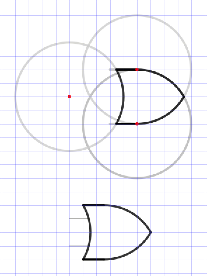
Click here for the .svg source image, drawn on a 1 mm grid with 5 mm major grid lines.