Inverting opamp exercise
Open this simulation model of an inverting amplifier.
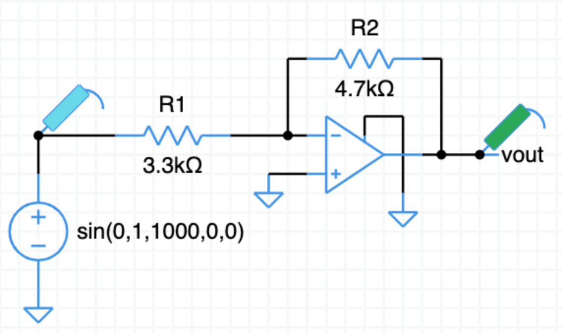
What is the expected gain of this amplifier?
show answer
From the inverting opamp video, the gain expression for the amplifier is,
$v_o = -\dfrac{\text R2}{\text R1}\,v_{in}$
Fill in the resistor values,
$v_o = -\dfrac{4.7\text k}{3.3\text k}\,v_{in}$
$v_o = -\dfrac{4.7}{3.3}\,v_{in}$
$v_o = -1.4\,v_{in}$
The gain is $-1.4$. The output is inverted with respect to the input and is $1.4$ times larger.
Click on TRAN to run a transient simulation.
Does the simulation match your gain calculation?
Design an amplifier with a gain of $-10$.
Hint: Pick new values for either or both of $\text R1$ and $\text R2$.
Change the values of the resistors in the simulation and run TRAN again.
Verify your new amplifier has the gain you expect.
Starting from scratch with a blank schematic, design and simulate an inverting amplifier with a gain of $-1$.