Ideal opamp exercise
Introducing the ideal opamp,
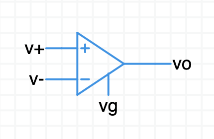
An opamp is a differential amplifier. It measures the difference in voltage between its two input ports, amplifies that difference, and puts the result on the output port.
$(\sf{vo} - \sf{vg}) = \text A \,(\sf v$+ $\, - \,\,\sf v$-$)$
The output voltage $\sf{vo}$ is generated relative to the $\sf vg$ pin. $\sf vg$ is usually connect to ground.
See the Circuit Sandbox opamp model for more details.
Prepare a simple opamp circuit
Open this incomplete schematic.
The gain of this opamp has been set low so you can see how a differential amplifier works.
Double-click on the opamp. Give it a name like “Op1”.
What is the gain of this opamp?
show answer
The initial gain setting is $\text A = 10$.
Opamps have gains in the many $1000$’s, but we start low to get a feel for how it works.
Add another ideal opamp from the parts bin. Open up its properties with a double-click.
What is the gain of an opamp fresh from the parts bin?
show answer
A default ideal opamp in Circuit Sandbox has a gain of $\text A = 30{,}000$.
You can leave it at this value most of the time.
It is common for real-world opamps to have a gain of $\text A = 100{,}000$ or more.
We don’t need this opamp any more. Please delete it.
Let’s build a circuit,
- Connect the opamp ground reference pin to ground.
There are two voltage sources to drive the opamp inputs.
What are the DC values of these two supplies?
- Connect $\sf v$+ to the opamp’s + input.
- Connect $\sf v$- to the opamp’s - input.
- Connect the bottom side of both opamps to ground.
finished schematic
Do the rest of this exercise with your own schematic.
If you want you can compare yours to the one I drew — Willy’ schematic.
Before you run a simulation, figure out in your head what $\sf vo$ will be.
Hint: Use the opamp equation, $(\sf{vo} - \sf{vg}) = \text A \,(\sf v$+ $\, - \,\,\sf v$-$)$
Perform a DC operating point analysis.
What is $\sf vo$?
show answer
$(\sf{vo} - \sf{vg}) = \text A \,(\sf v$+ $\, - \,\,\sf v$-$)$
$(\sf vo - 0) = 10 \,(1.1 - 1.0)$
$\sf vo = 10 \,(0.1)$
$\sf vo = 1\,\text V$
The output voltage is $10$ times the difference between $\sf v$+ and $\sf v$-.
Change $\sf v$+ to $1.3\,\text V$. What is going to happen to $\sf vo$?
Anticipate the answer in your head, then do a DC simulation.
Change $\sf v$- to $0.8\,\text V$. What is going to happen to $\sf vo$?
Anticipate the answer in your head, then do a DC simulation.
Change $\sf v$- so it is greater than $\sf v$+. What is going to happen to $\sf vo$?
Anticipate the answer in your head, then do a DC simulation. Try several values.
Change $\text A$ to $20$. What is going to happen to $\sf vo$?
Anticipate the answer in your head, then do a DC simulation.
You demonstrated the basic operation of a differential amplifier.
This ideal opamp model has a ground reference pin (which most opamps don’t have). It has no power supply pins, so the output isn’t limited. The output can go to any value that obeys the opamp equation from above. That makes this ideal model kind of fanciful. For real opamps the output voltage doesn’t exceed the power supplies. We will practice with realistic opamps in the next exercise.
Advanced
High gain
Change $\sf v$+ or $\sf v$- so the difference between them is $10\,\text{mV}$.
Change $\text A$ to $100{,}000$. It is not hard to design an opamp with gain like this.
What will happen to $\sf vo$?
Anticipate the answer in your head, then do a DC simulation.
This is kind of a trick question. With the gain so high, even the smallest input differential voltage will cause a huge output. For real-world opamps the output increases until it slams into either the top or bottom power supply and stays there. This is called output saturation.
Ground reference pin
The voltage you attach to the opamp’s ground pin, $\sf vg$, does not have to be $0$. It might be better called the output reference pin. This pin determines the output voltage when the input voltages are identical, when $\sf v$+ $= \sf v$-.
Open this schematic in a new browser tab. The opamp’s inputs are connected together and both are connected to ground. The $\sf vg$ pin is connected to a voltage source you can adjust.
Run a DC operating point simulation to verify $\sf vo$ is $0$.
Change the value of the voltage source to move the opamp’s output reference pin to a different voltage.
Set the $\sf vg$ voltage source to $1\,\text V$. Run another DC. What happens to $\sf vo$?
Try other voltages, including negative values.
What is this for? Traditionally, opamps are operated dual-rail with symmetric $+$ and $-$ power supplies. In symmetric dual-rail systems ground potential is centered between the rails. Sometimes you prefer to operate an opamp between a positive power supply and ground. This is called single-rail or single-supply operation.
With single-rail you center the output between the positive supply and ground. For example, if the power supply voltage is $\sf{Vs}$+ $= 5\,\text V$ you want the output to be $\sf{vo}$ $= 2.5\,\text V$ when the input difference is zero. To set this up, generate a steady $2.5\,\text V$ and apply it to the ground reference pin as shown in this single-rail example. Run a DC and observe the output when the inputs are the same. $2.5\,\text V$ is now the reference for measuring your signal—think if it as “signal ground.”
Summary
Now you have a feel for how a differential amplifier works. The amplifier had modest gain. In the upcoming opamp videos the gain will be really high. You will learn how to take advantage of high gain to design useful circuits featuring an opamp.
The ideal opamp model is a good place to start when learning opamp circuit configurations. It’s ideal behavior saves you from having to worry about the nitty-gritty details of real opamps. That comes after you have the basic circuit configurations down pat.